What I really need is a small, light, easy to transport boat to get out onto the water on at a moment’s notice. I have Nick Schade’s book “Building Strip-Planked Boats”. In the book there are the plans for a double-paddle canoe, “Nymph”. I was drawn to the design because of the tumblehome gunnel of the design. I took Nick’s advise and stretched the design out from 10′ (for 150 lbs) to 12’8″ to accomindate larger paddlers. (I figure that between myself and my stuff, its 225 lbs.) Even with this extra length, I should be able to get the canoe on and off of my roof racks and to the water without any problems.
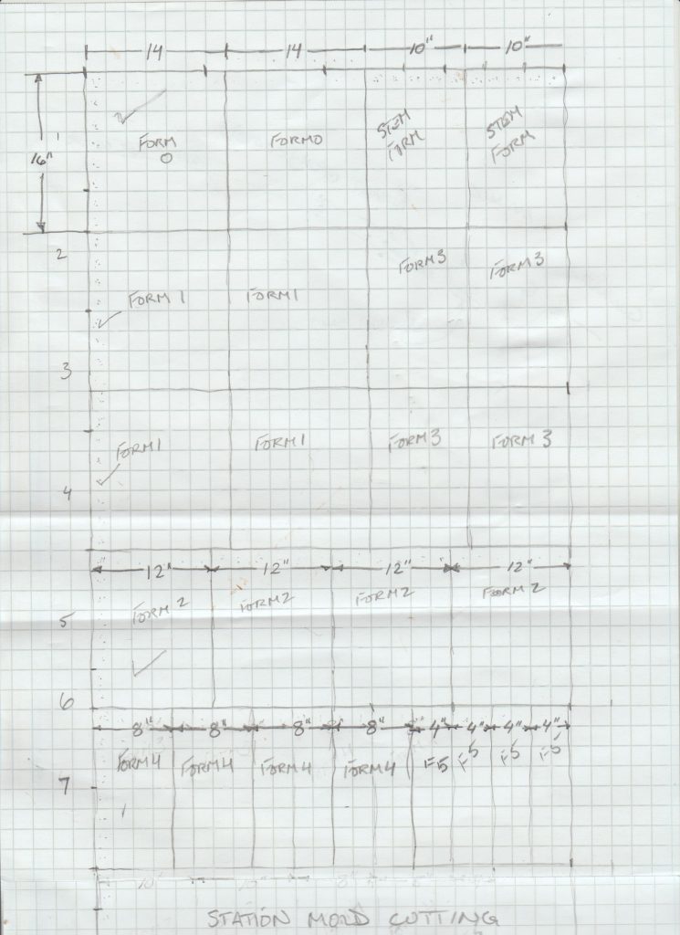
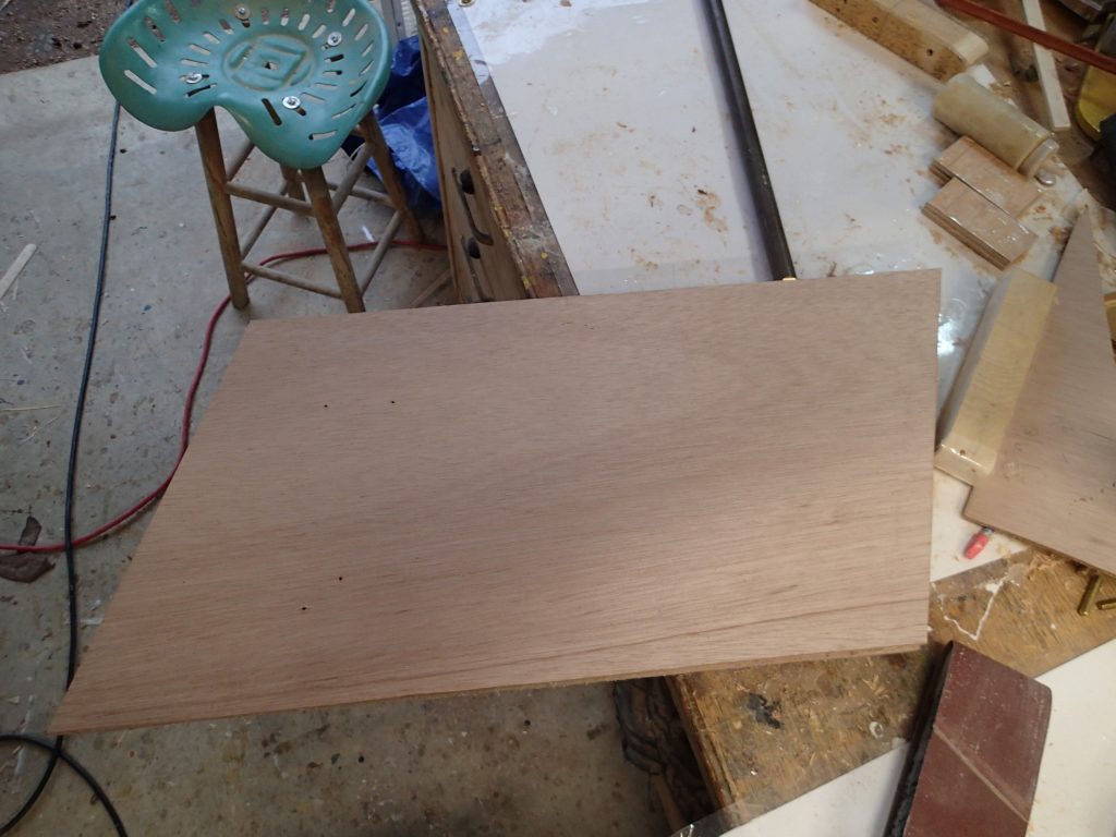
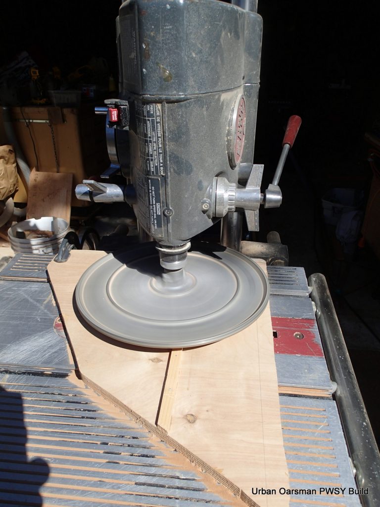
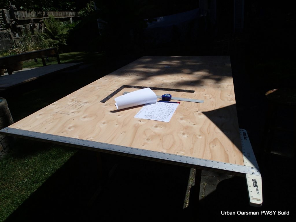
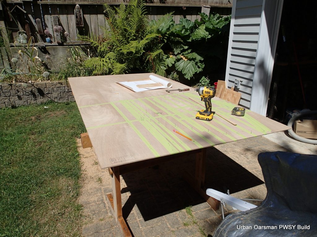
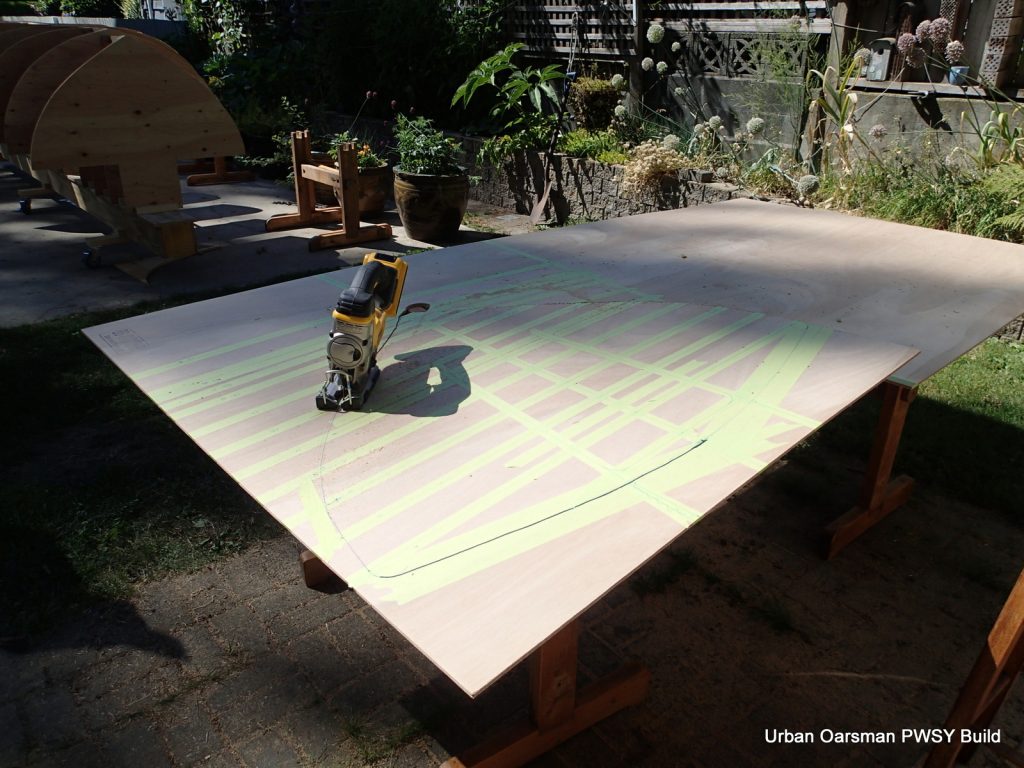
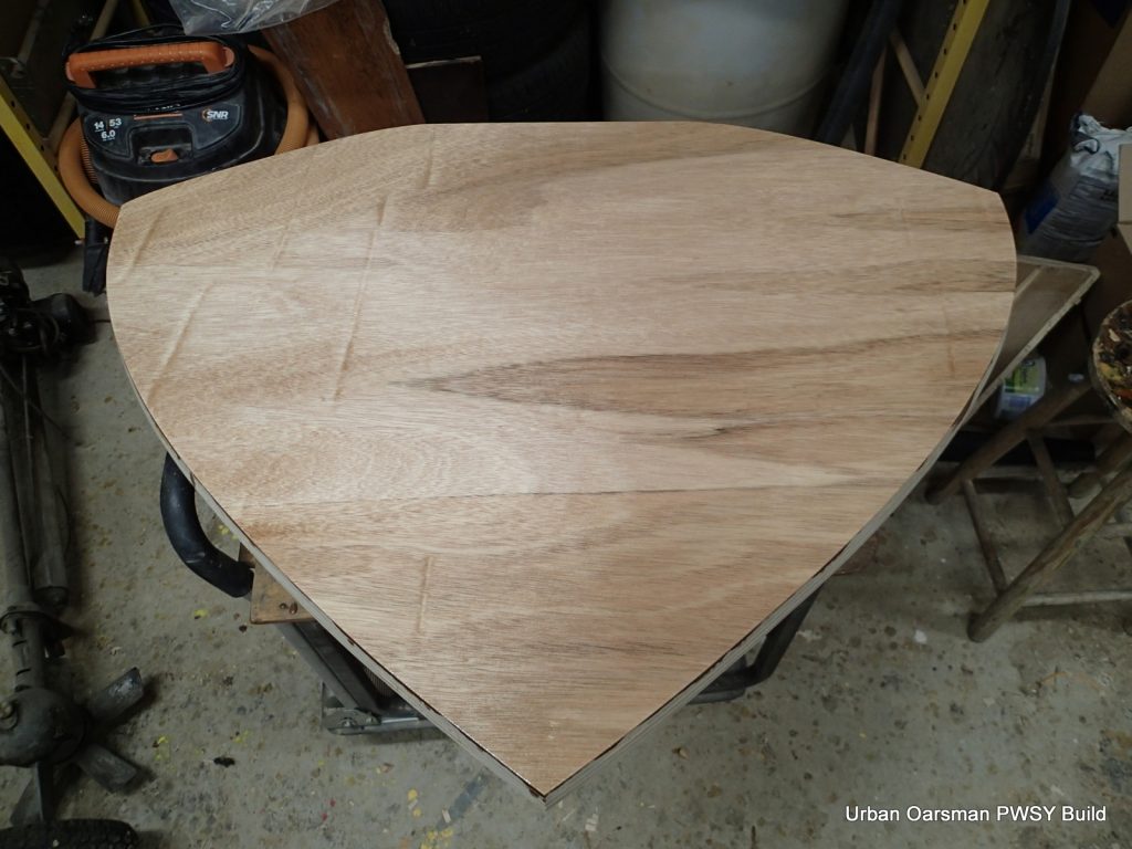
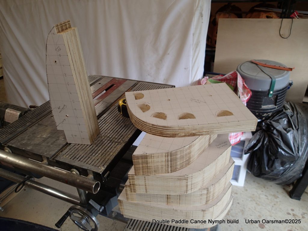
The plywood cutting plan for the forms. All out of one sheet. In the past, I have had a hard time getting both sides of a form (station mold) to be the same. I am trying something new, cutting out “half” forms to get both sides of the form the same. I will draw only one side of the form onto the plywood and cut the “half” forms out on the bandsaw and finish with my 10″ sanding disk. This way both sides of the form should be identical. I will fix two sides together to get each complete form. Both sides of the canoe are identical, so there will be one form #0 (centre form), two “form #1, #2, #3, #4 and #5”, and two stem forms.
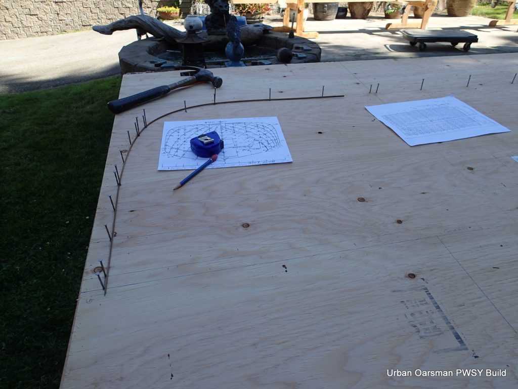
This will be stacked onto the other three form blanks so as to cut them out all at once and hopefuly get both sides of the forms the same.
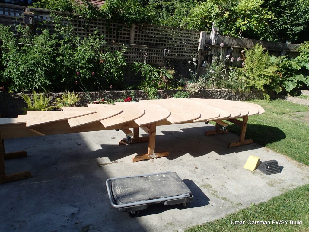
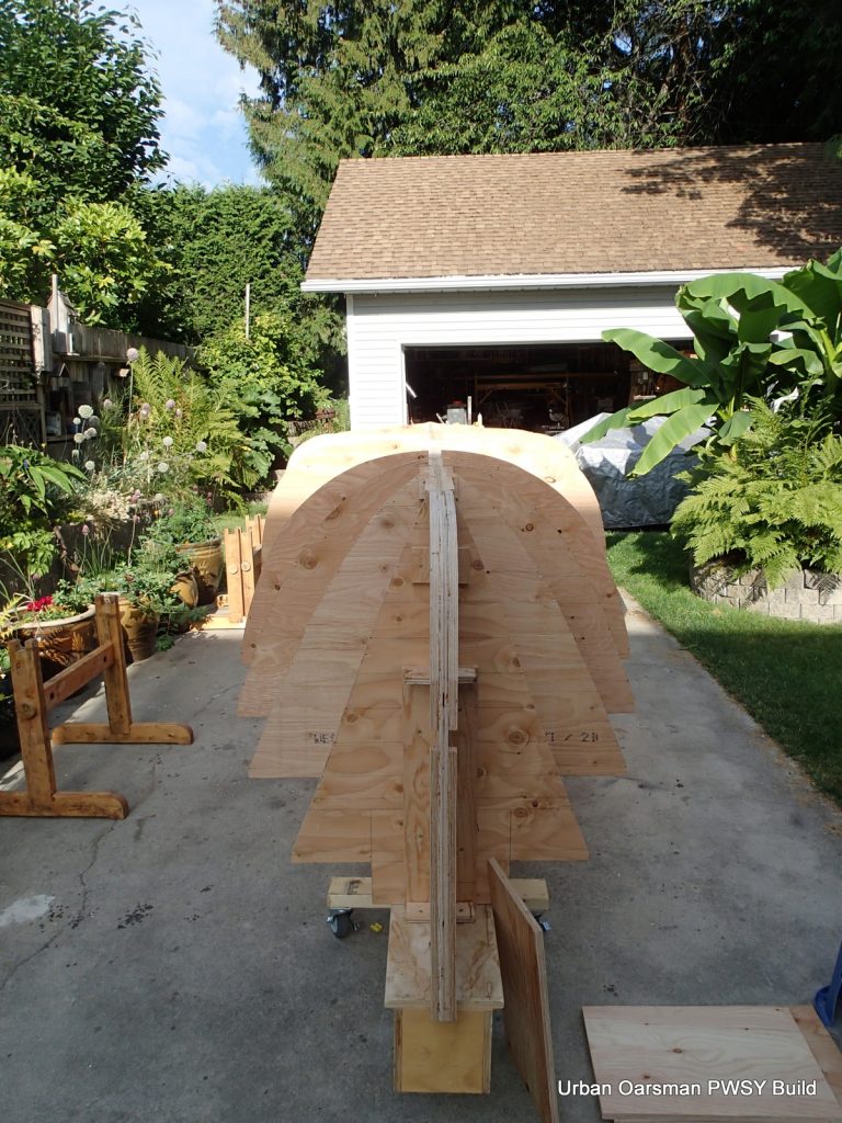
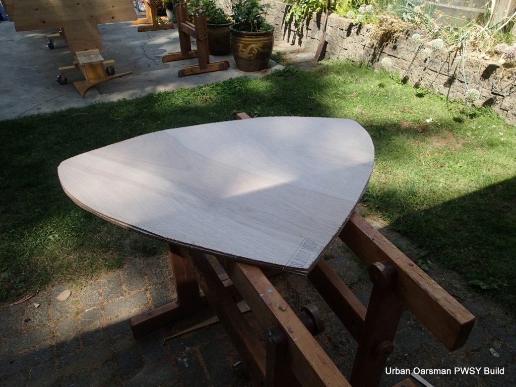
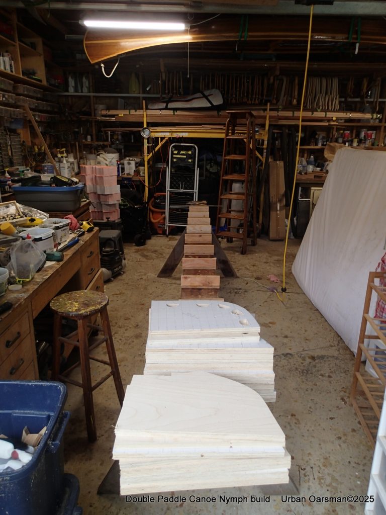
So I have cut out the forms on the bandsaw. There is a bow and a stern form, and four pieces each for forms #1, #2, #3, #4 and #5.
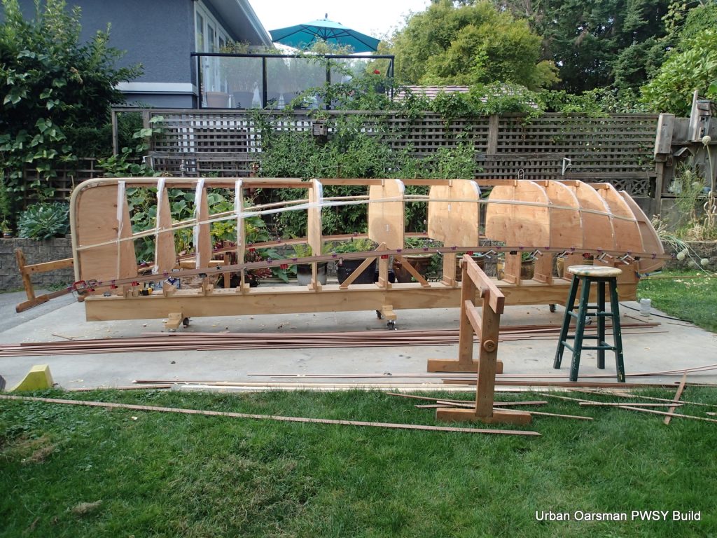
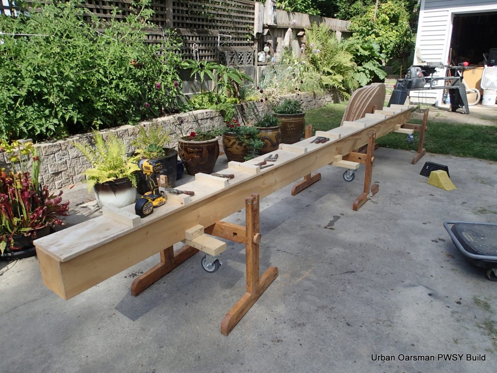
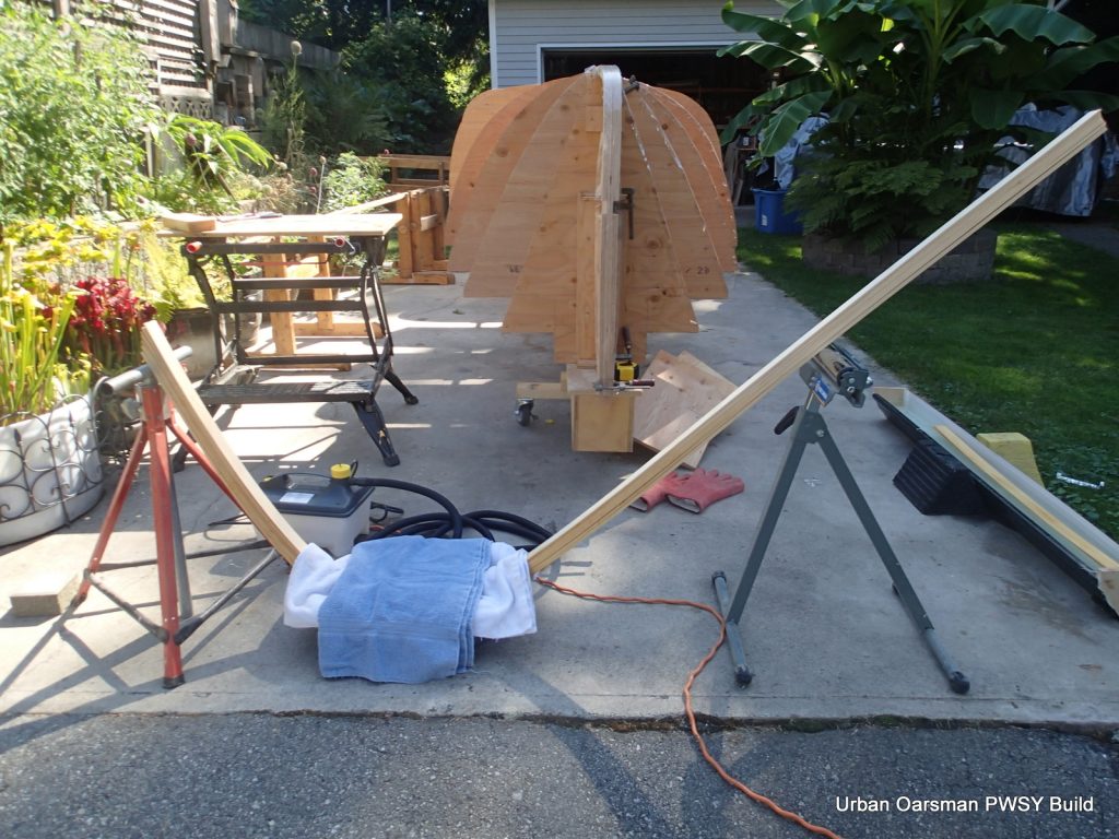
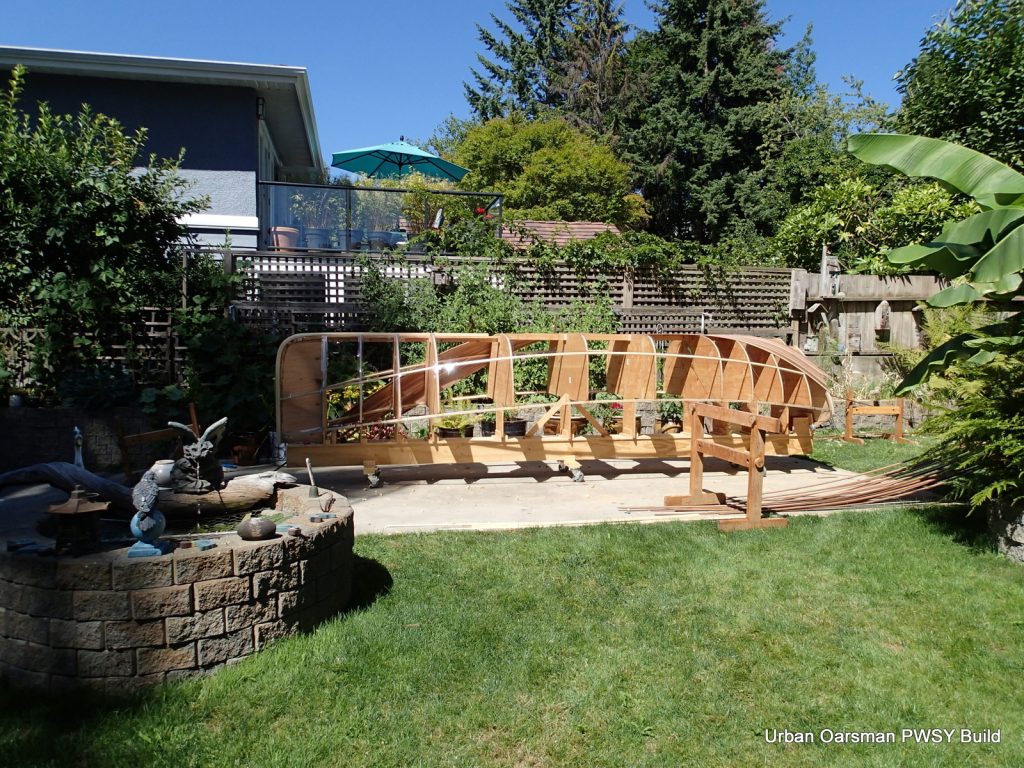
Having carefully measured, I screw the cross pieces onto the strongback at 12″ intervals. As Nick says in the book about changing the form spacing: “The stem forms would need a little bit of adjustment, but would be pretty close as is”. I stretched my bow and stern forms out an extra 4″ to get a smooth curve for the keel.
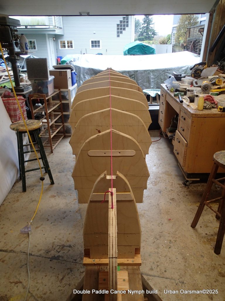
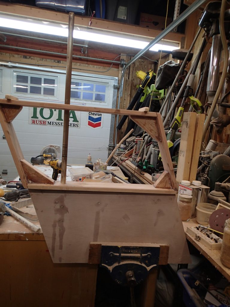
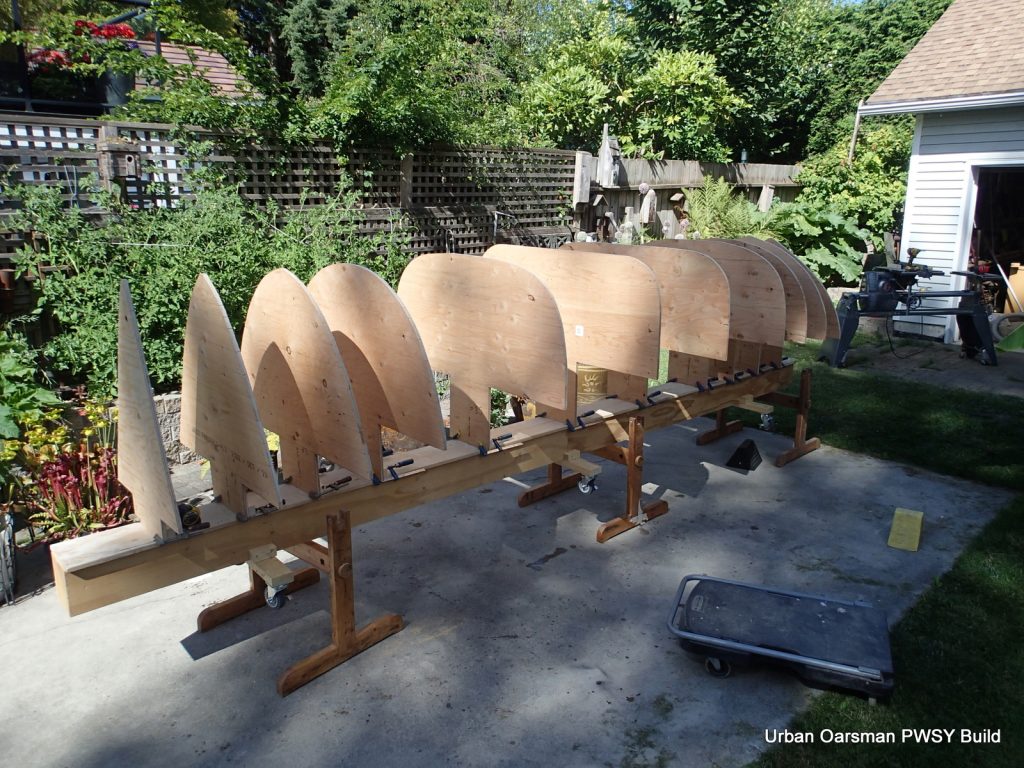
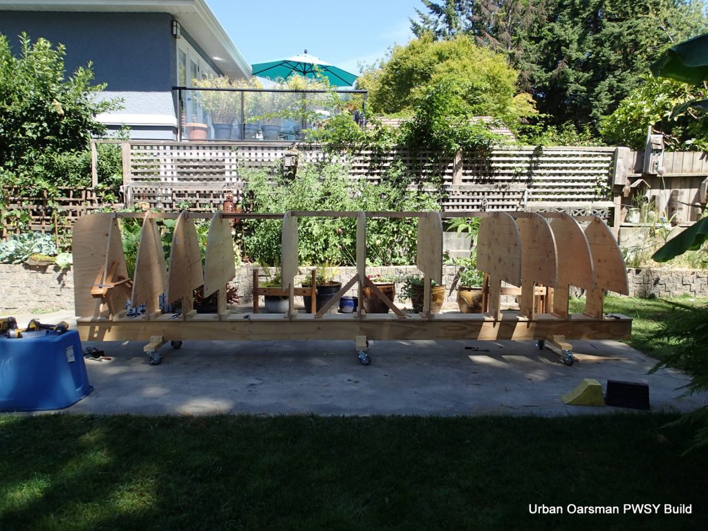
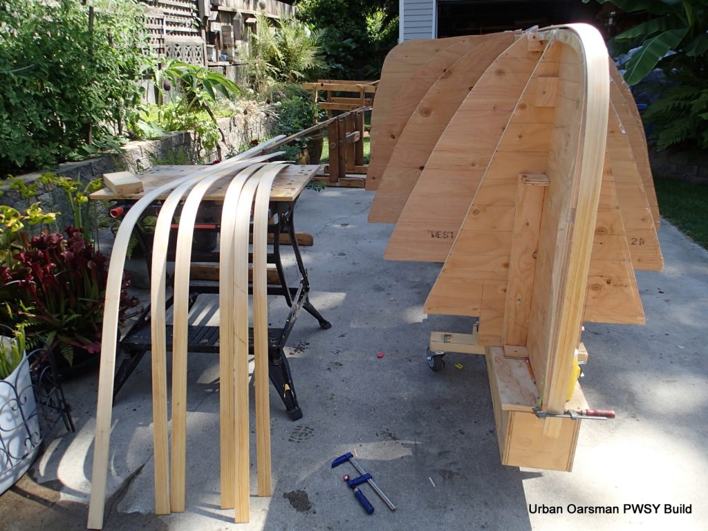
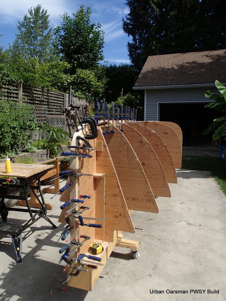
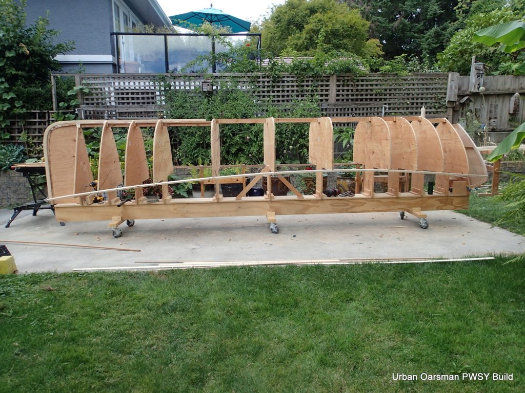
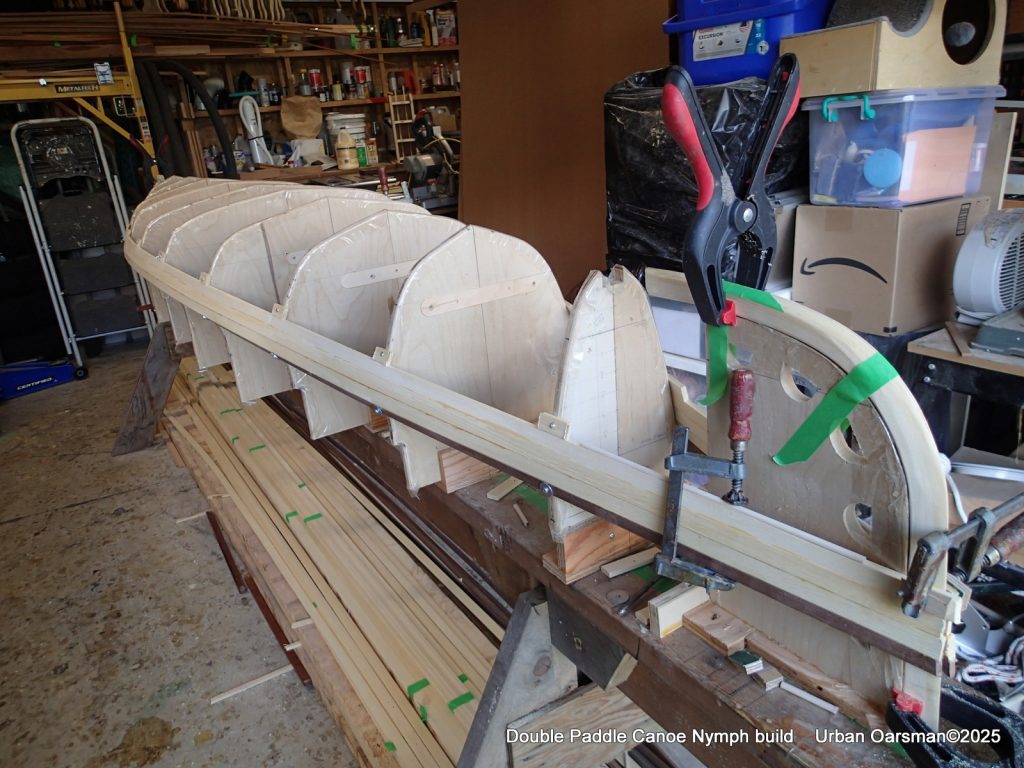
So here we are, the forms are in, aligned and ready for the bow and stern stems to be laminated in. If I was to do this again, I would make the forms go higher from the strong back to make access to the interior and the removal of the forms when planked, easier.
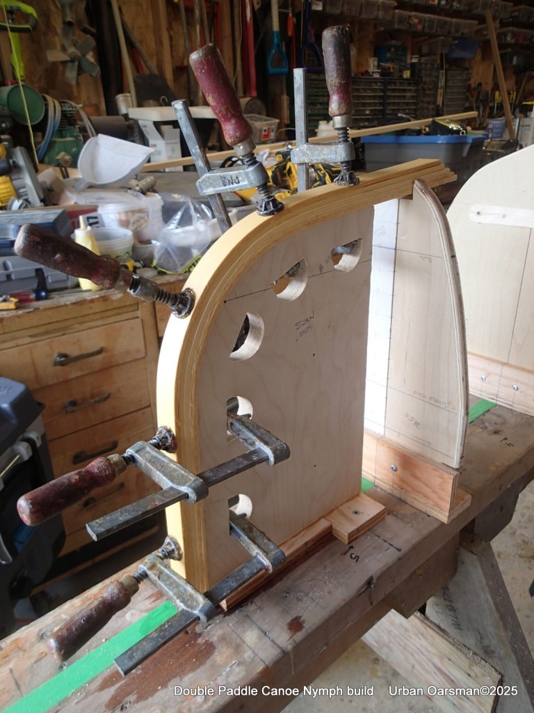
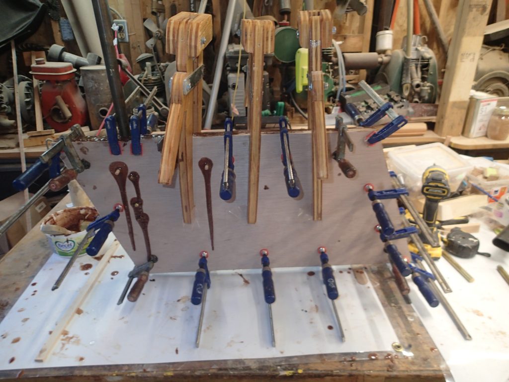
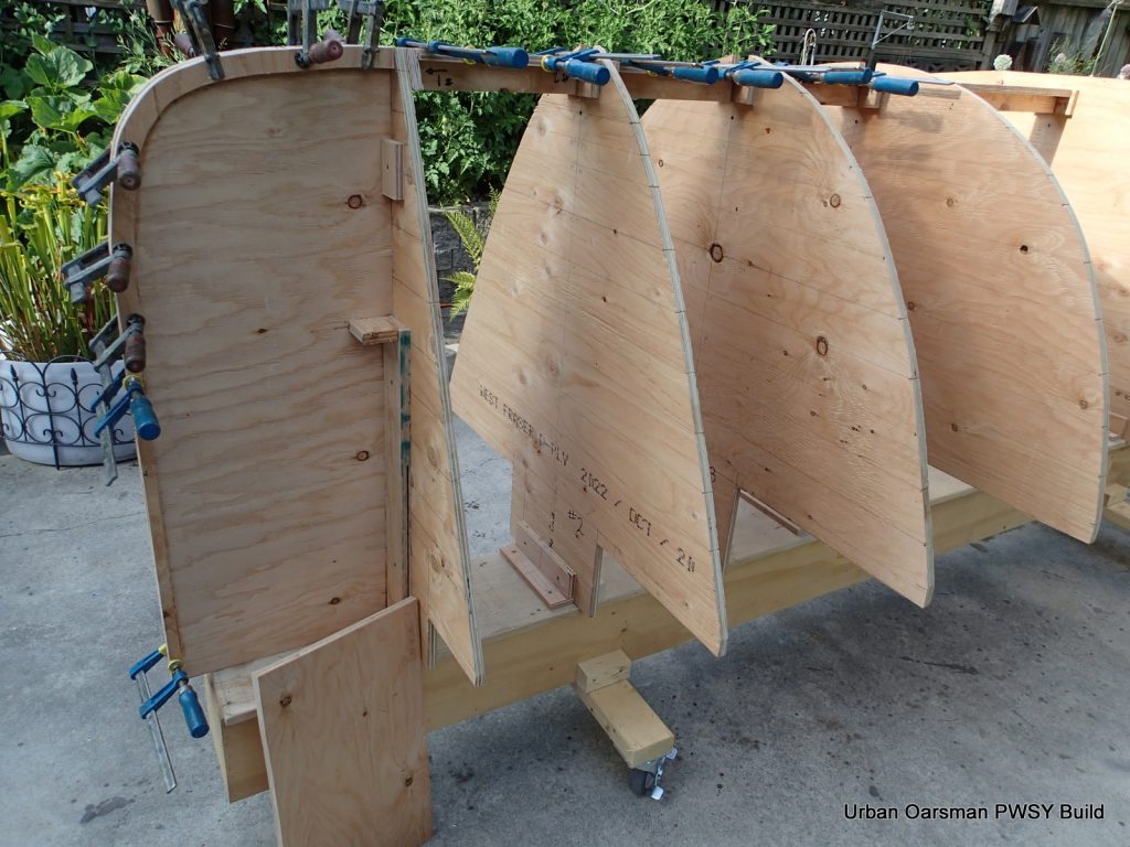
I used five strips of ¼” yellow cedar for the inside stem pieces, glued with Titebond 2. Packing tape keeps the stems from sticking to the forms.
Good squish-out for the glue, clamps on the sides to keep the strips aligned. All of the forms have packing tape on the edges so the glue does not stick to them.
In this photo you can see the packing tape on the forms and the packing tape applicator.
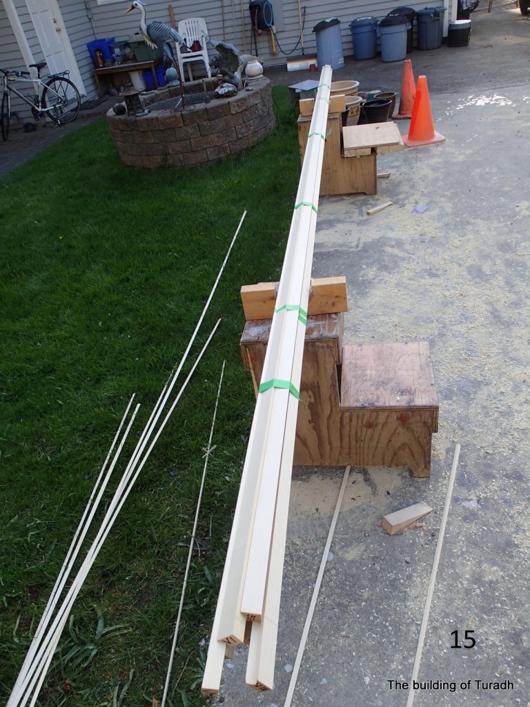
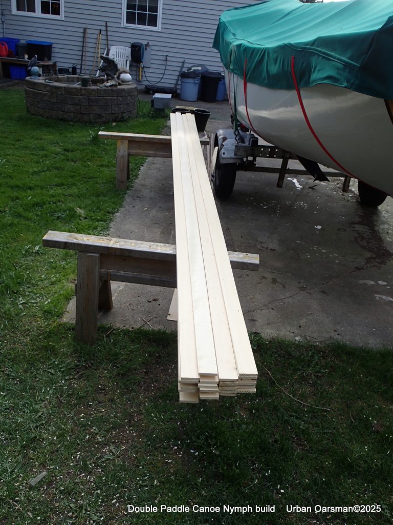
Bringing home yellow cedar and a walnut plank for the strips and for a double paddle or two.
I put the yellow cedar 2″ by 6″ planks through the planer and then cut them into strips. You can see some of the walnut scrap from cutting the walnut strips on the ground to the left.
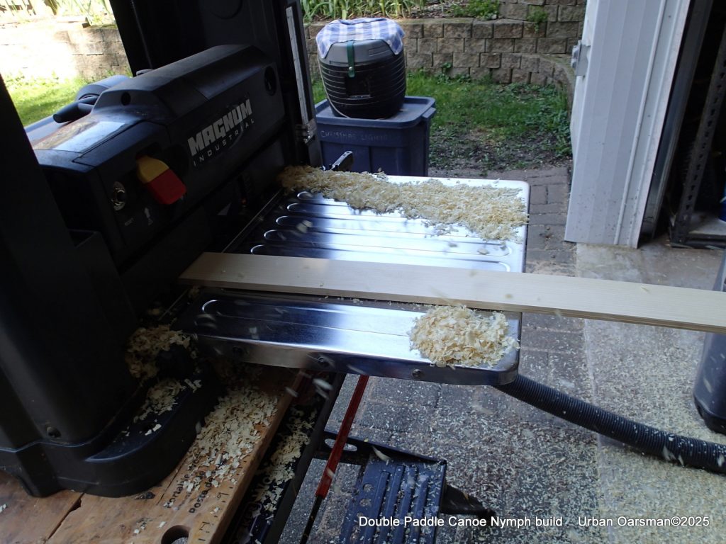
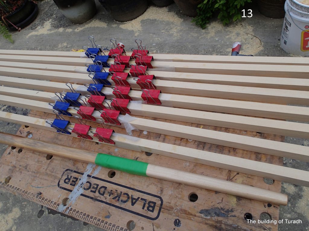
The procedure for strips is: 1). Plane the rough planks smooth and to the same dimensions. 2). Cut the planks into strips. 3). Plane the double-wide stips into the thickness you want. 4). Cut the double-wide strips in half to give you the width you want.
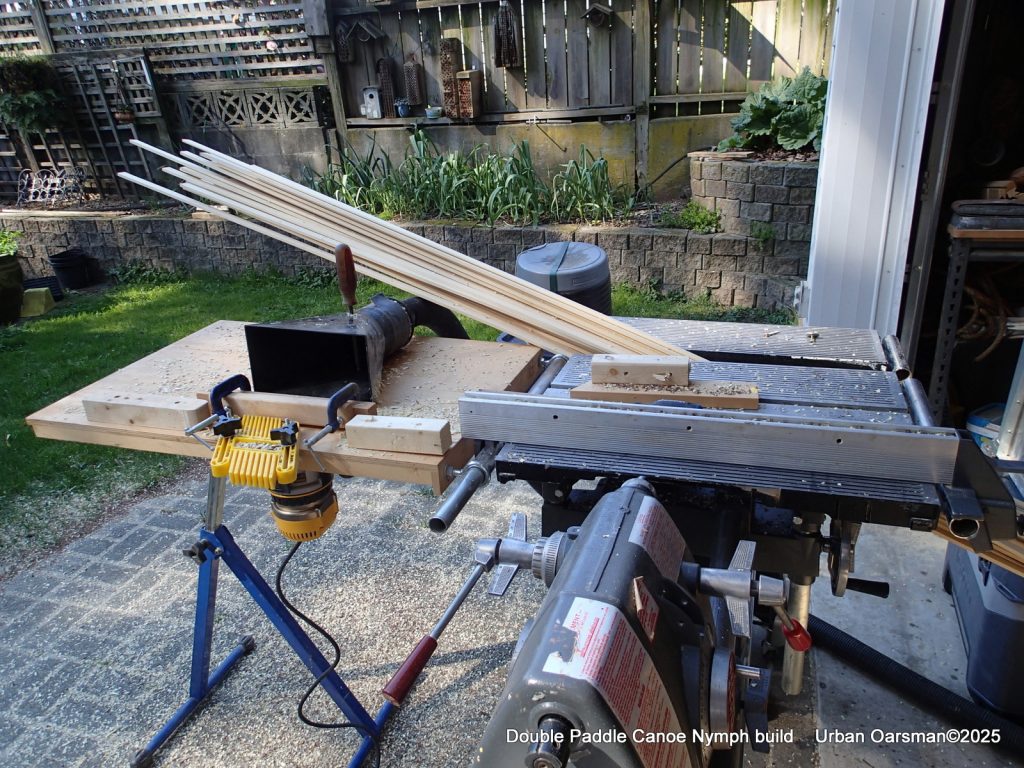
After ripping to the correct width, the bead and cove get cut.
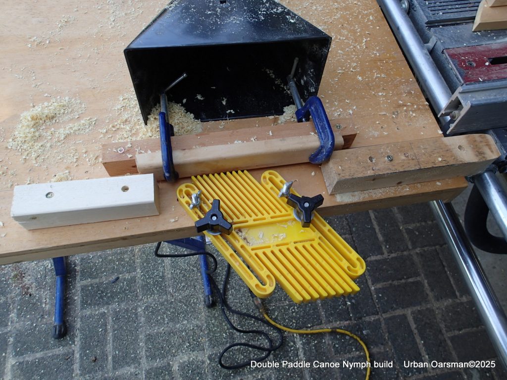
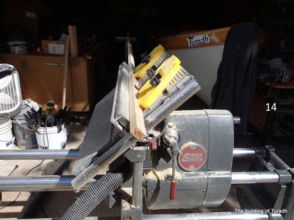
This is my ad-hoc bead and cove jig. I cut the bead first and the cove second. The cove is much more fragile than the bead. The router is hung under the table and the router bit is covered by the jig.
Having cut enough strips, time to plank.

One of the things I liked about the design was the contrast between the walnut and (in the book) basswood strips. I do not have ready access to basswood, so, I substituted yellow cedar for the basswood. This will give me a similar look and should actually be a little stronger.
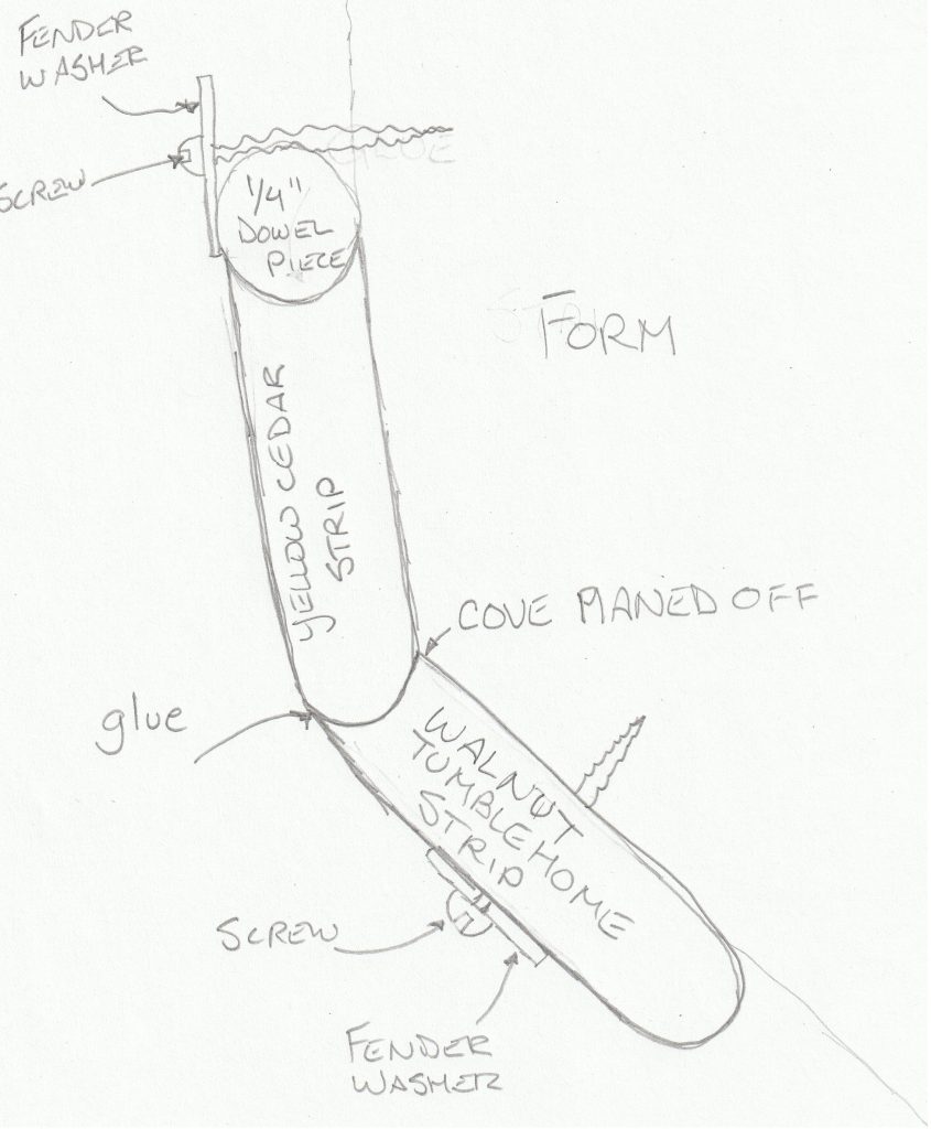
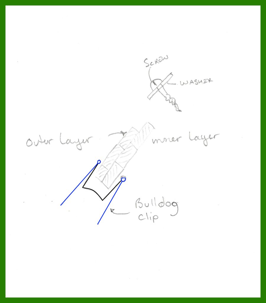
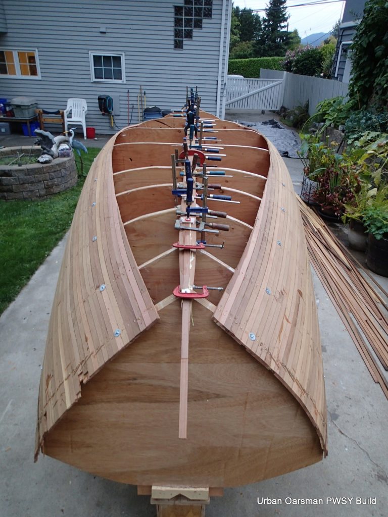
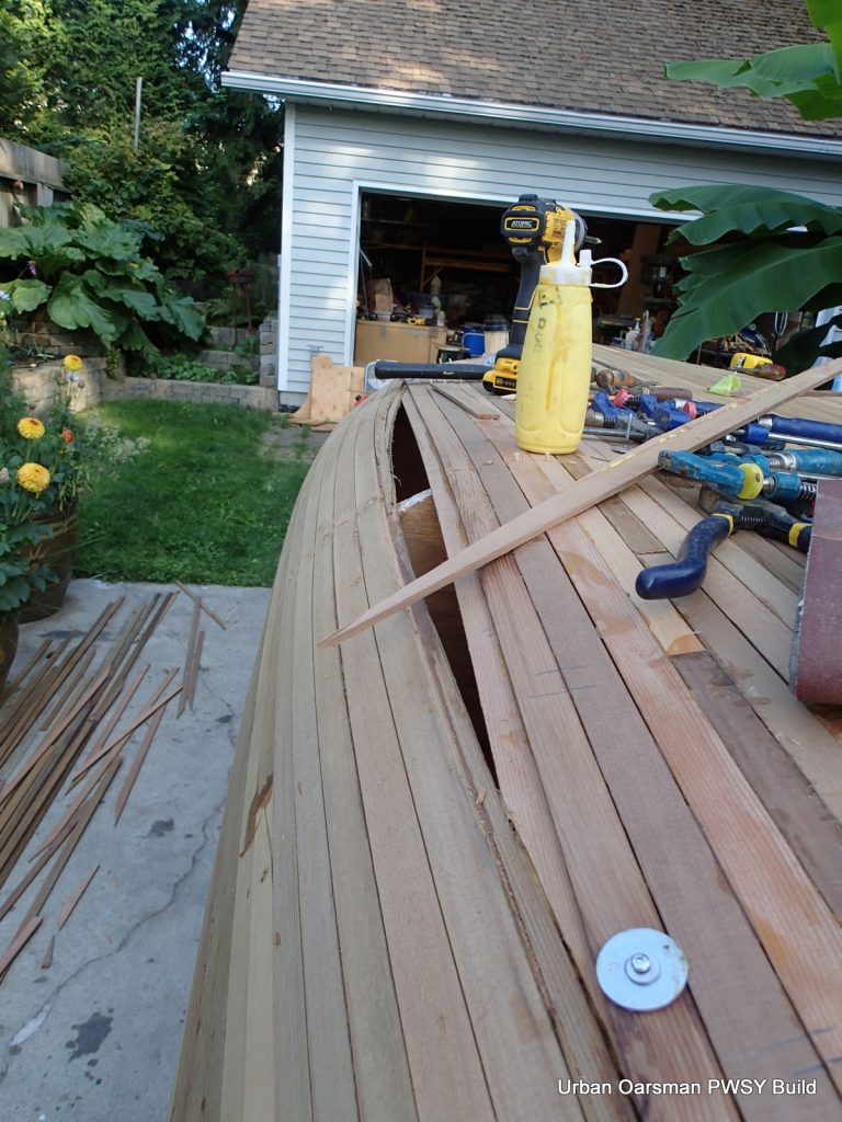
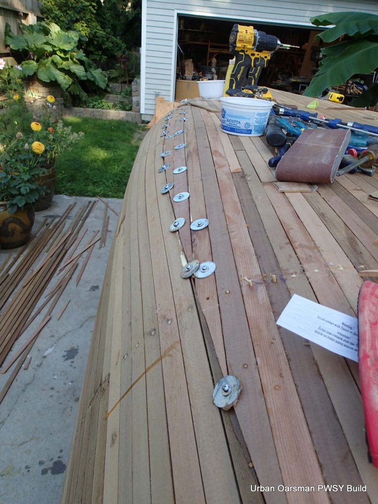
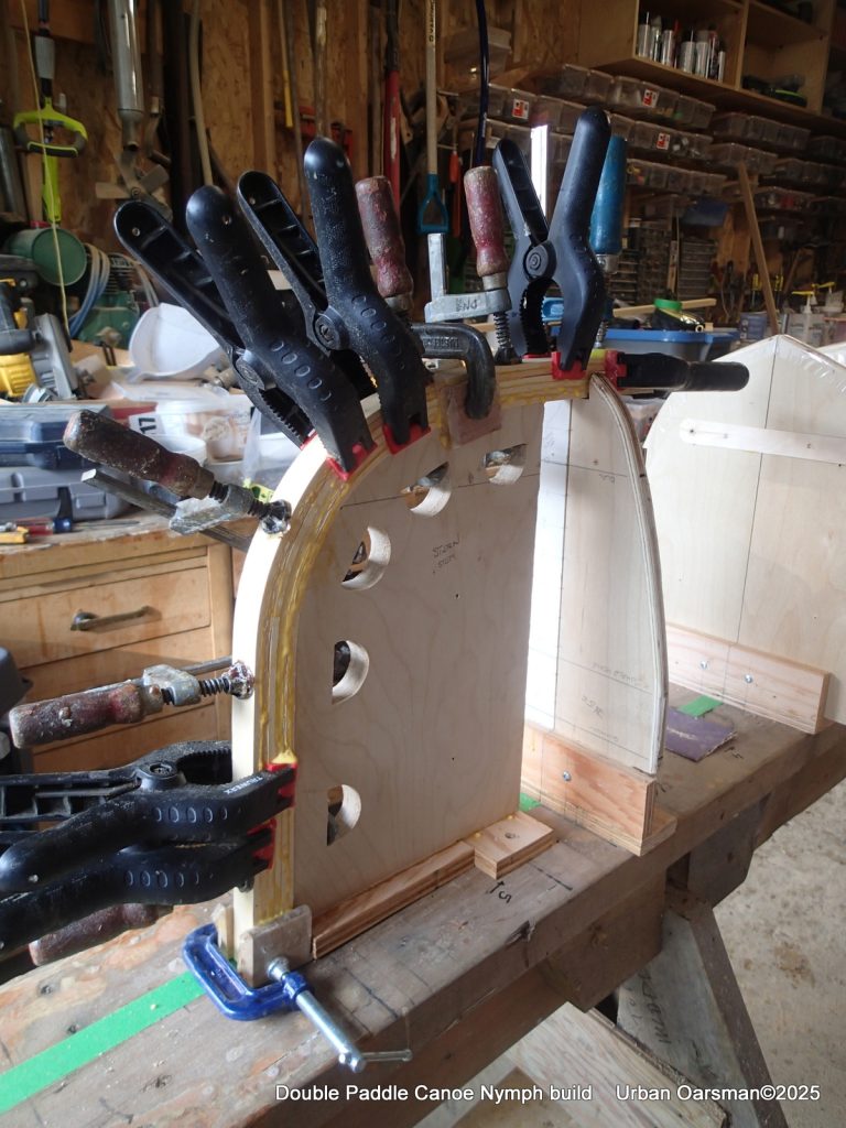
I had a very hard time at the tumblehome fitting the strips. I ended up cutting off the inside part of the cove on the yellow cedar strip so the walnut strip bead would fit snugly into the cove of the yellow cedar strip. I attached the walnut strip first, using screws and fender washers screwing the strip onto the forms. I would later plug the screw holes. I put glue into the walnut strip cove and used fender washers and screws to hold the yellow cedar strip to the walnut one. The ¼” dowel supports one side of the fender washer, the strip the other. I did not put any staples or screws into the strips other than the first walnut one.
Clamps hold the cedar strip to the walnut one at the tumblehome point. Two spring clamps keep the stems aligned.
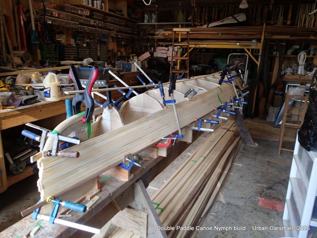
In this photo you can see the dowels being used to hold the strips together while the glue dries. The dowels fit into the cove of the strip. You can now clamp strips without destroying the cove. At the forms, a small block with a bead is being used to clamp the strips together. The advantage to doing it this way is you do not end up with having to remove a bunch of staples and have staple marks in your planking. I think that they would really show with the light cedar colour. The disadvantage is that you have to wait for the glue to cure enough to hold the strip before you can put the next strip on. Basically I was doing a pair (both sides) of strips every two hours or so.
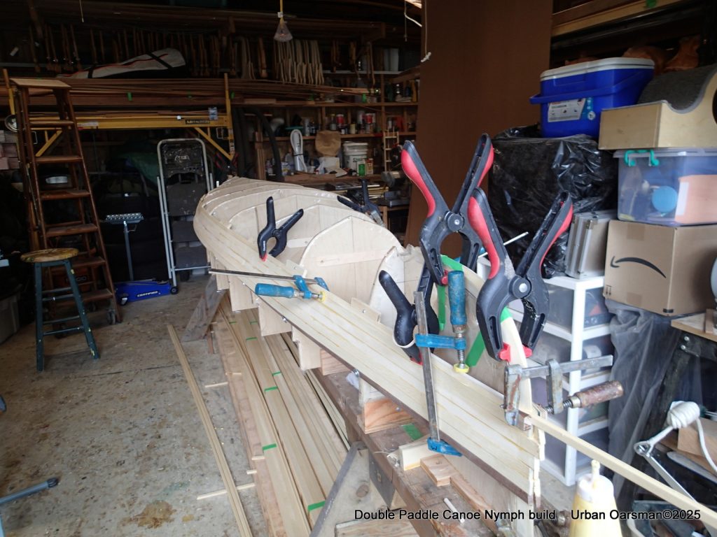
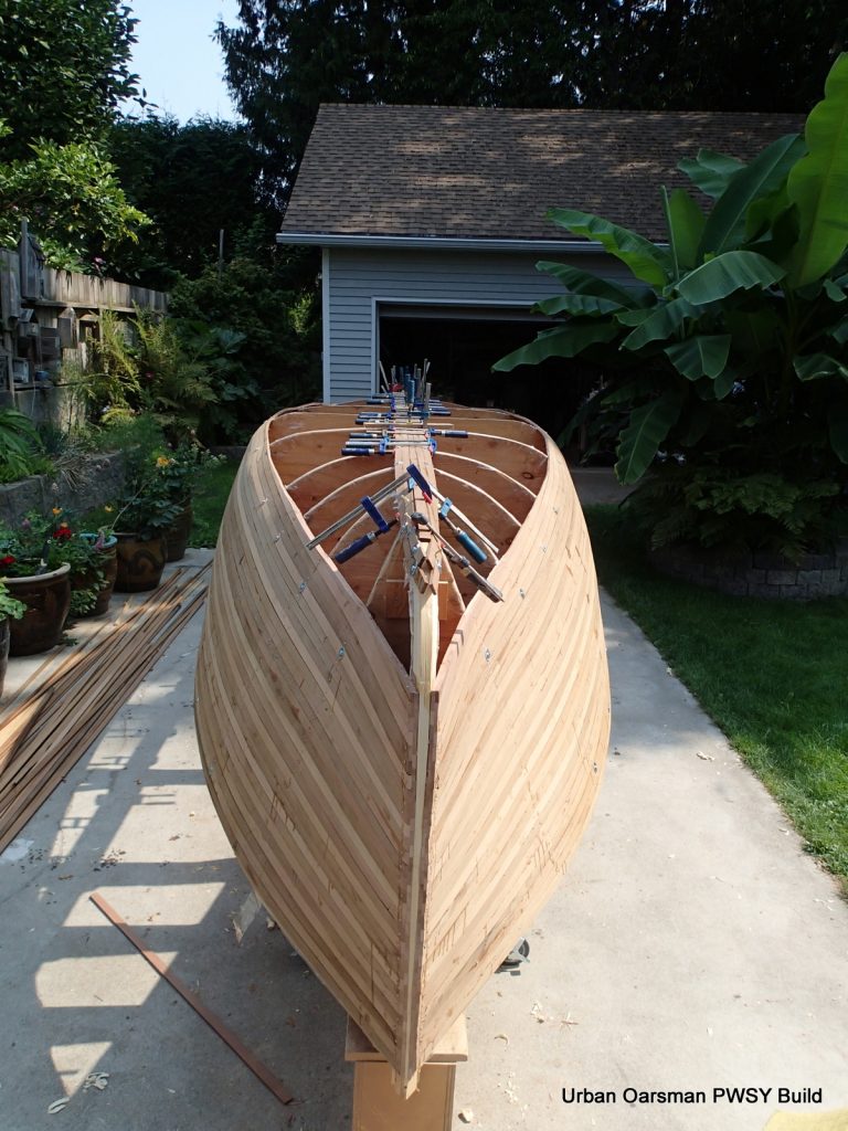
Continuing to strip the hull.
Continuing to strip the hull. I have stored the strips under the strongback. A mistake, as glue has dripped onto them.
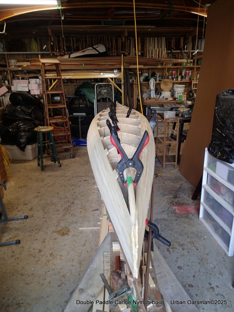
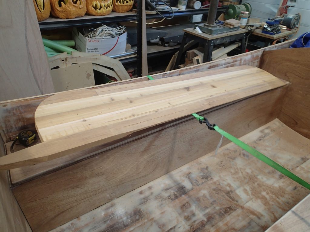
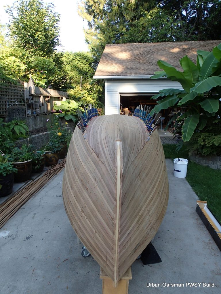
Going to “close the football”
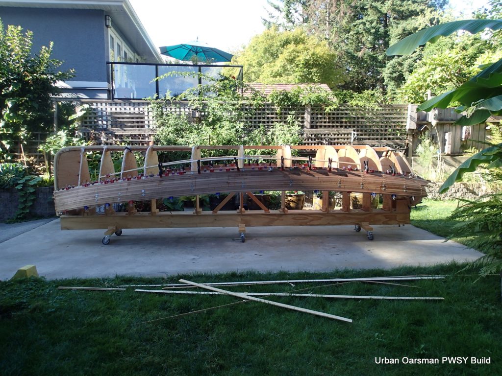
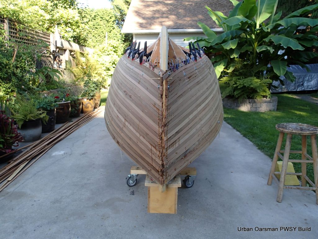
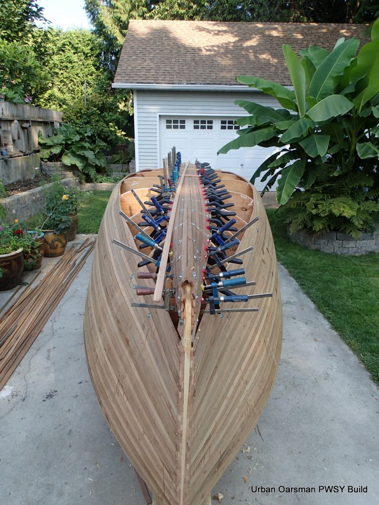
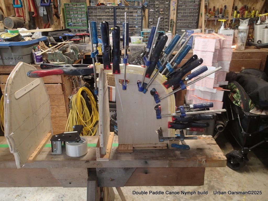
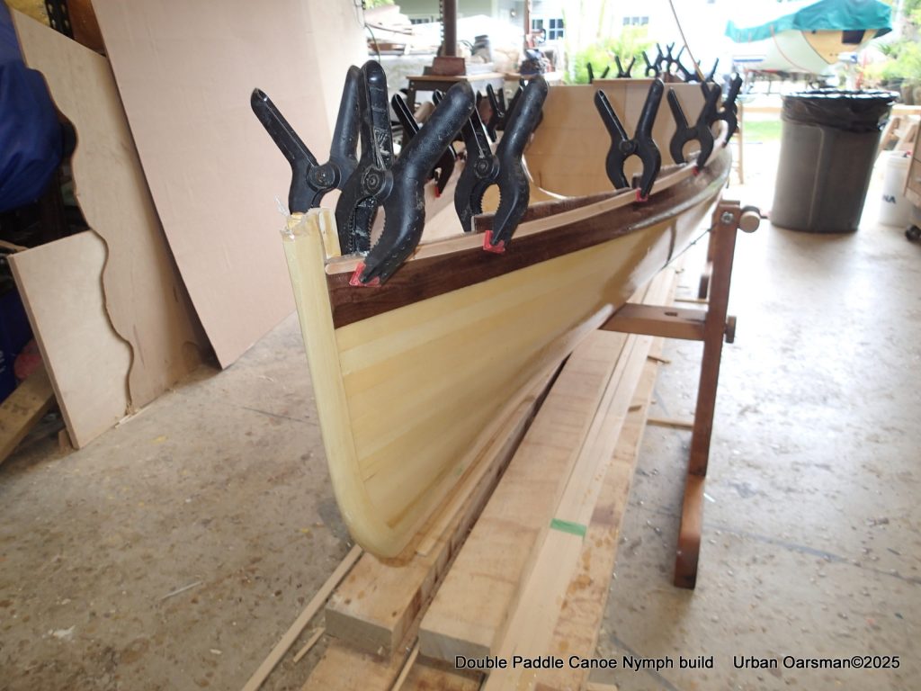
Closing the football and beginning to put the walnut strips on. Each one of the blocks screwed into the forms have a “bead” and are being used to clamp the strip onto the one below.
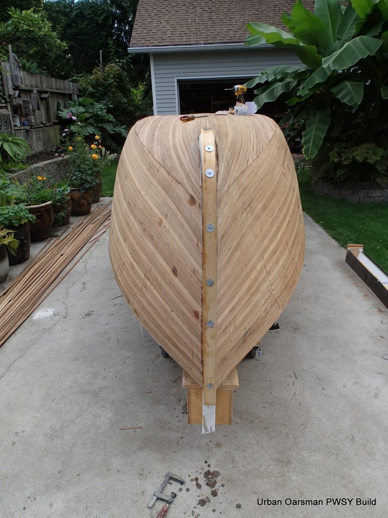
The walnut strips are going on. You can see the screws holding the first walnut strip to the forms. If I were to remove them, the shape of the tumblehome would get distorted. The hardest part of the build was getting the walnut strips to conform to the tumblehome shape.
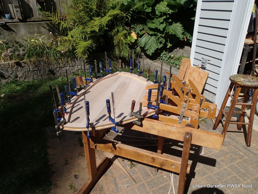
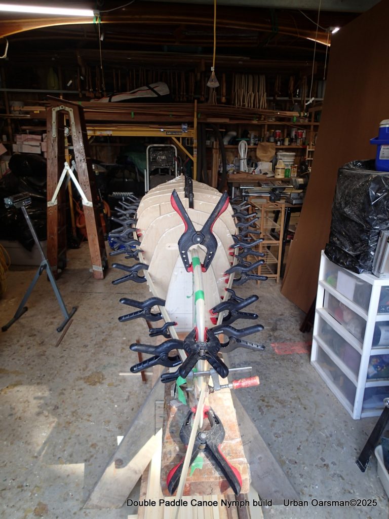
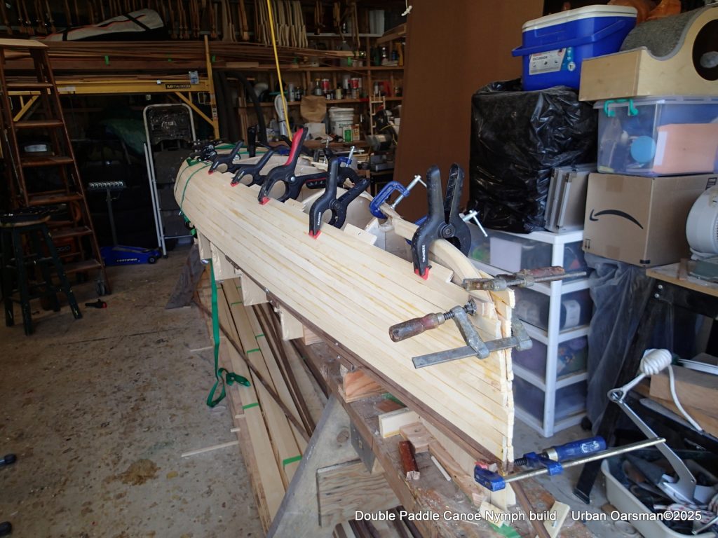
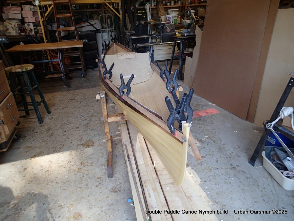
Putting the walnut strips on and closing the football. Good thing that I have a lot of clamps.
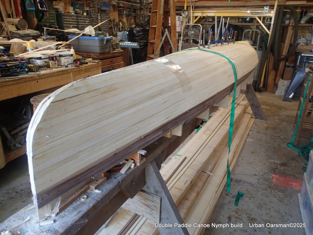
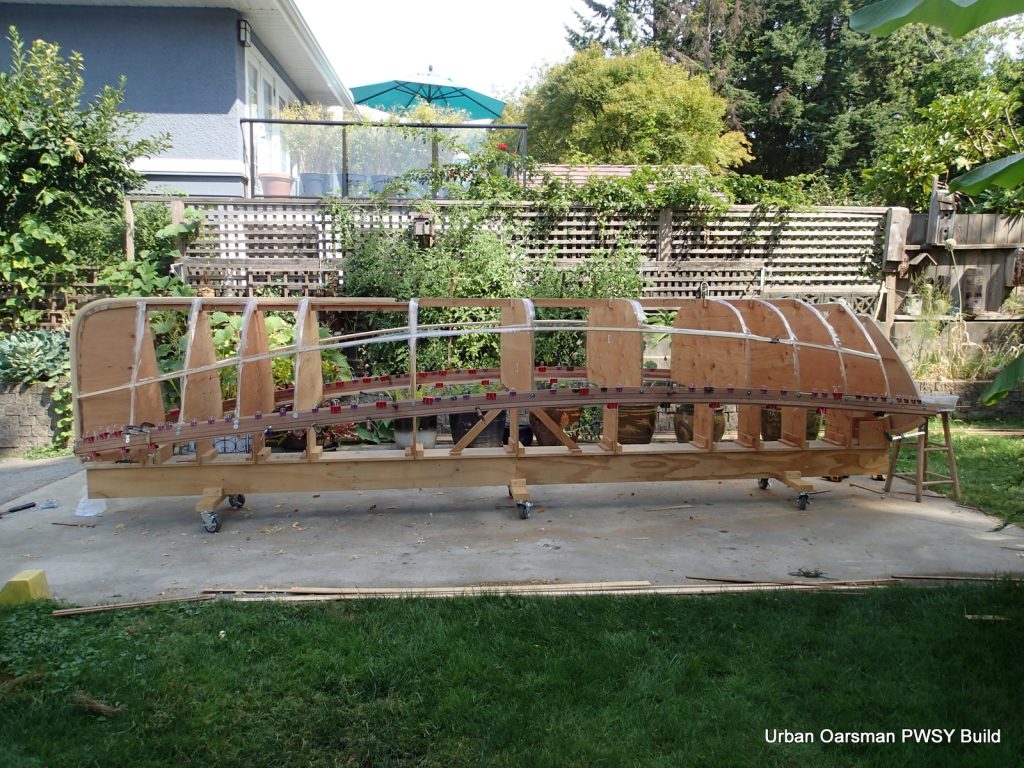
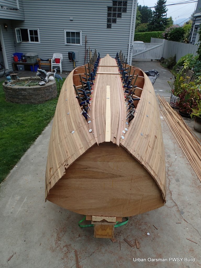
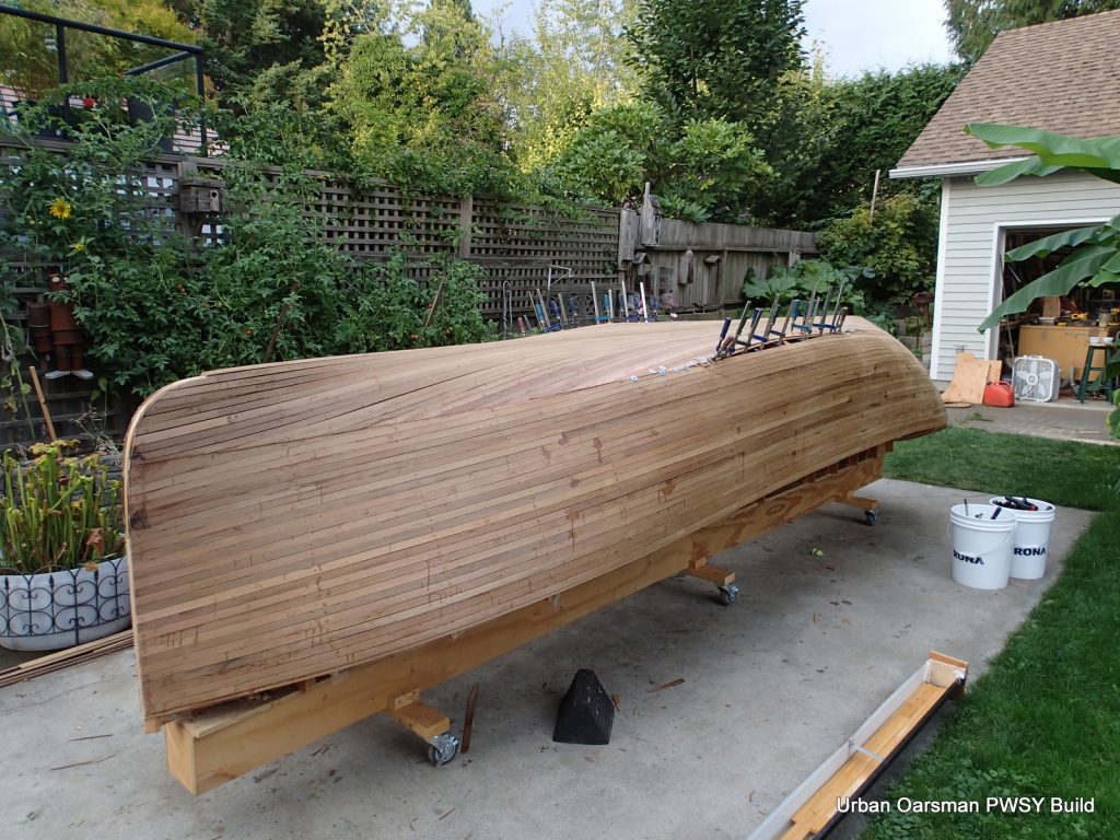
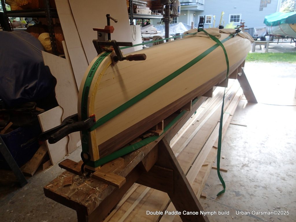
With the tumble-home strips done, I am using ratchet straps to help keep the strips tight to the forms. I am using packing tape so the glue does not stick to the straps.
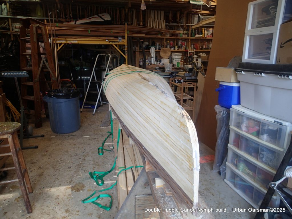
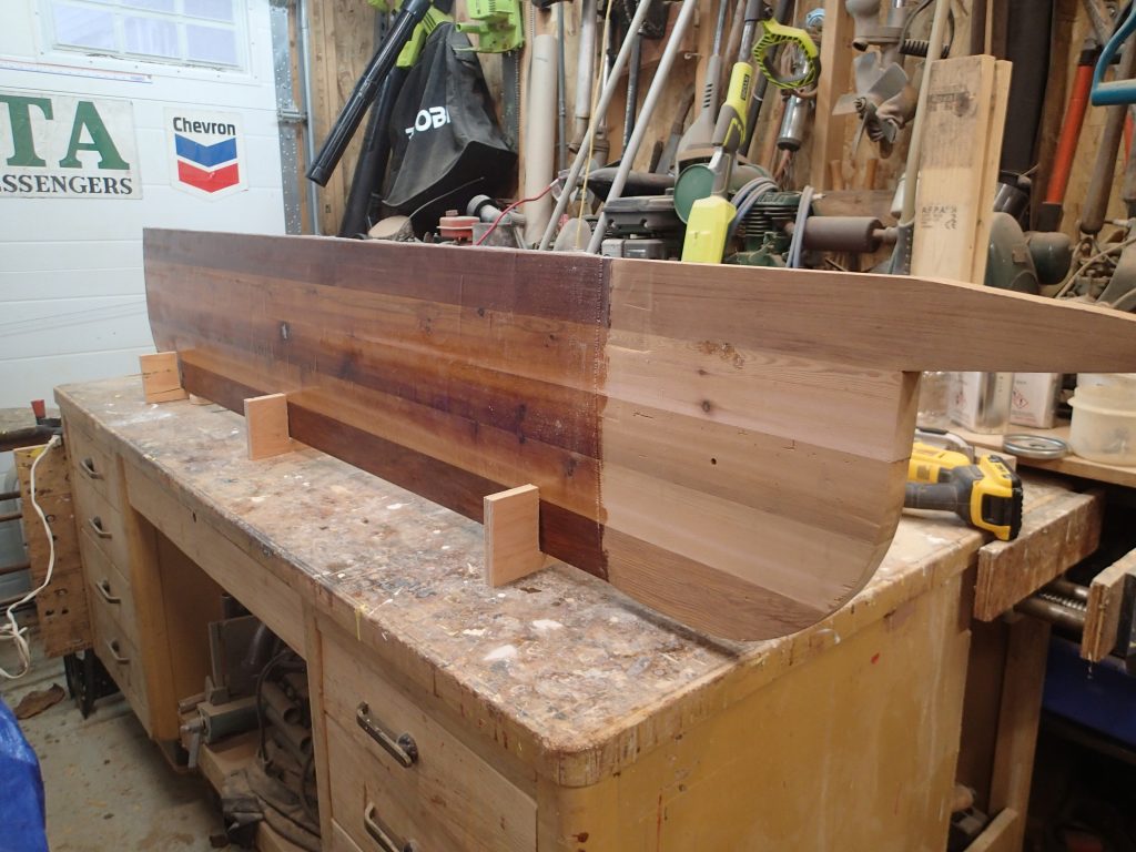
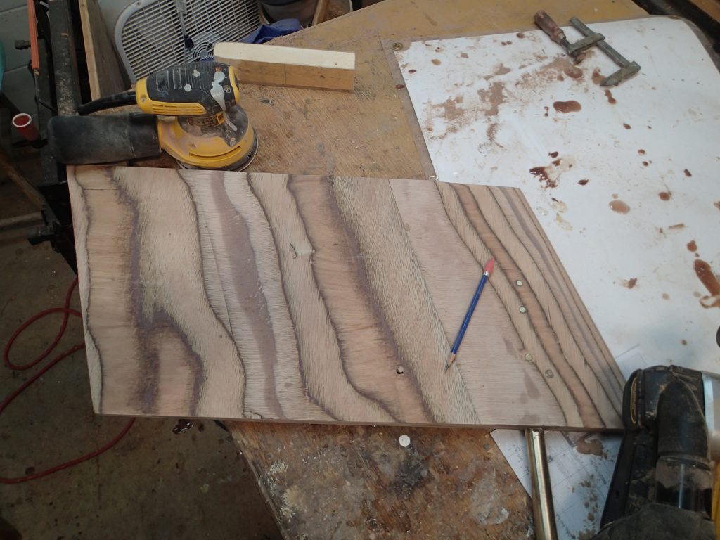
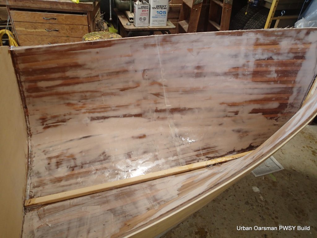
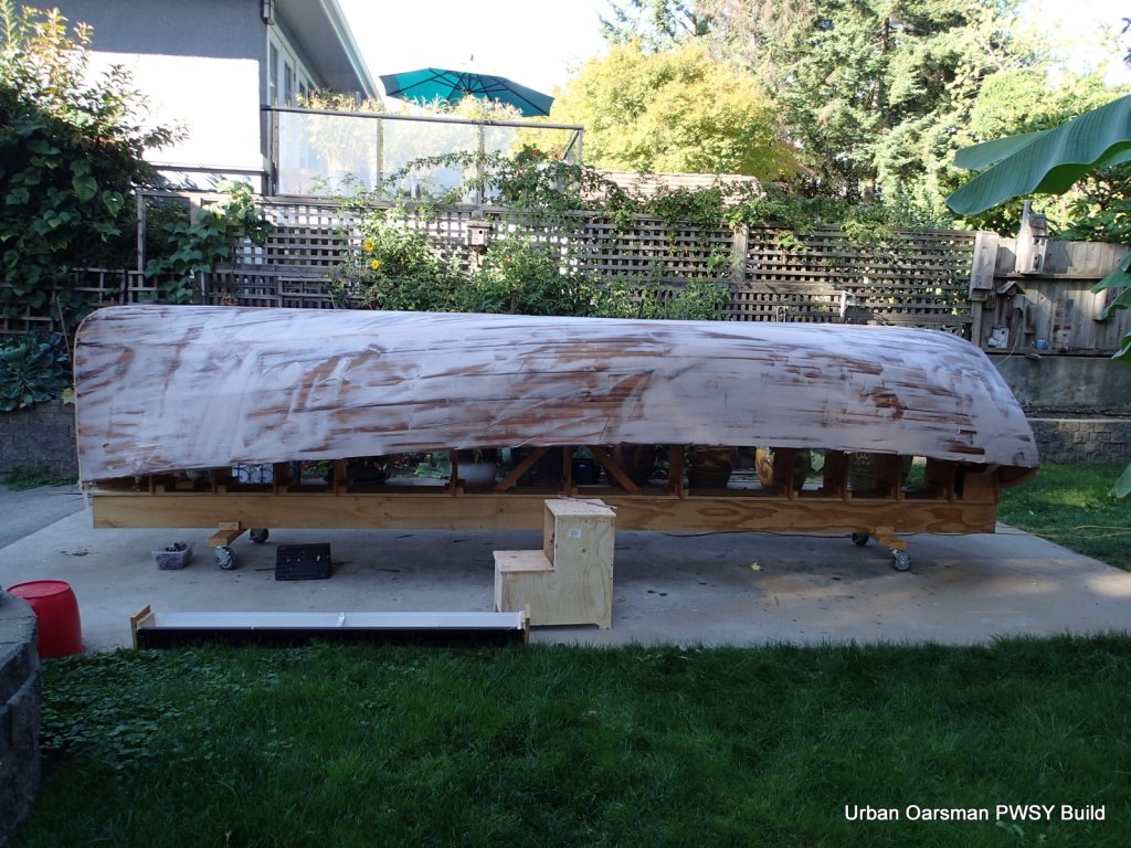
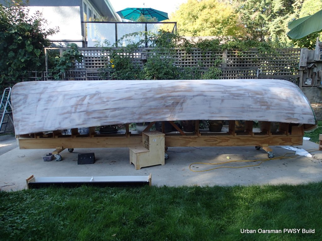
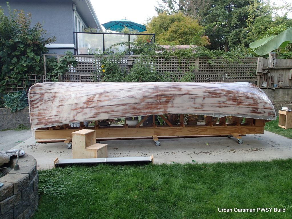
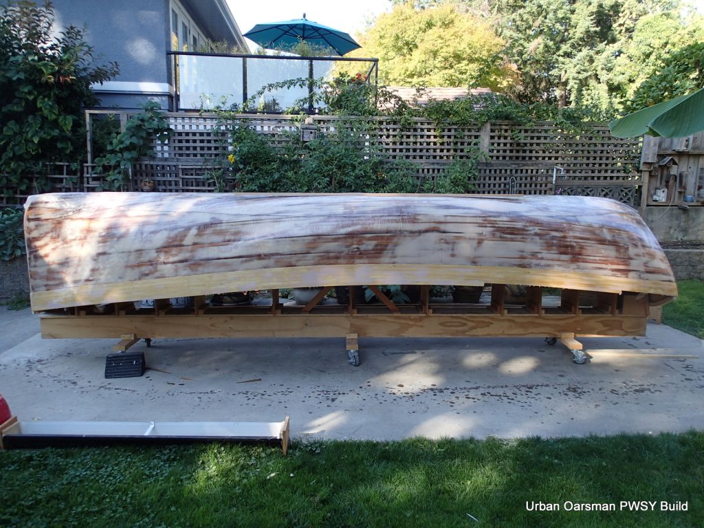
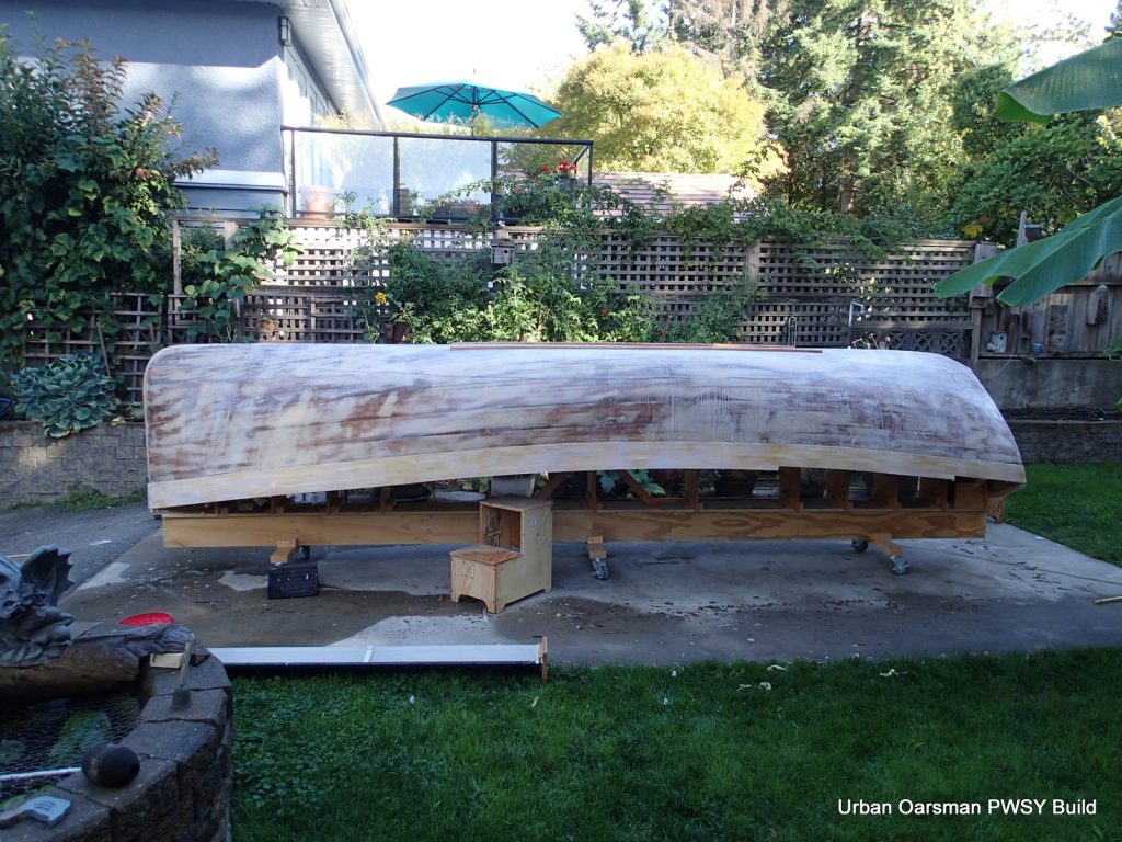
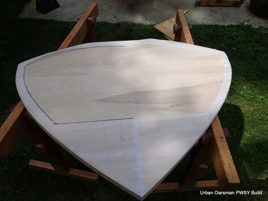
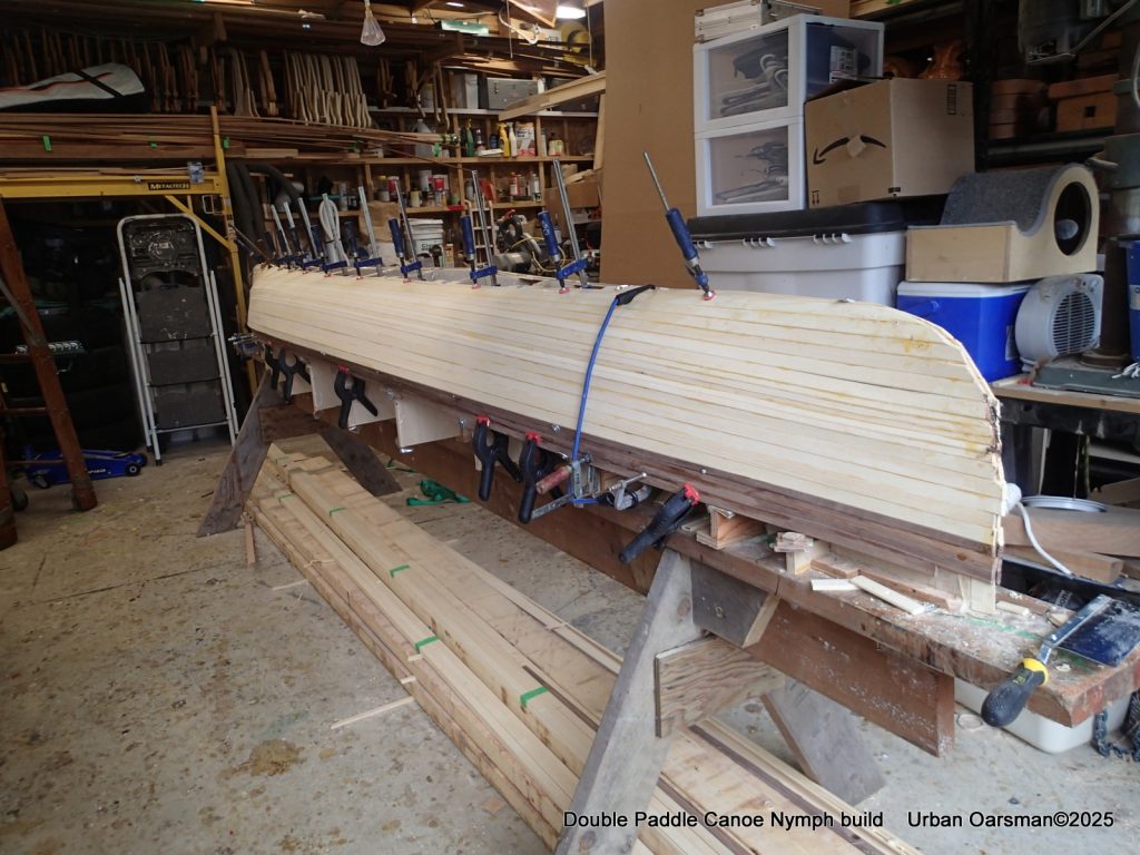
The football is filled and I have used some sawdust and glue as a filler where I did not get the strips just right. The next step is to sand the hull smooth and prep for laminating the outer stems onto the hull.
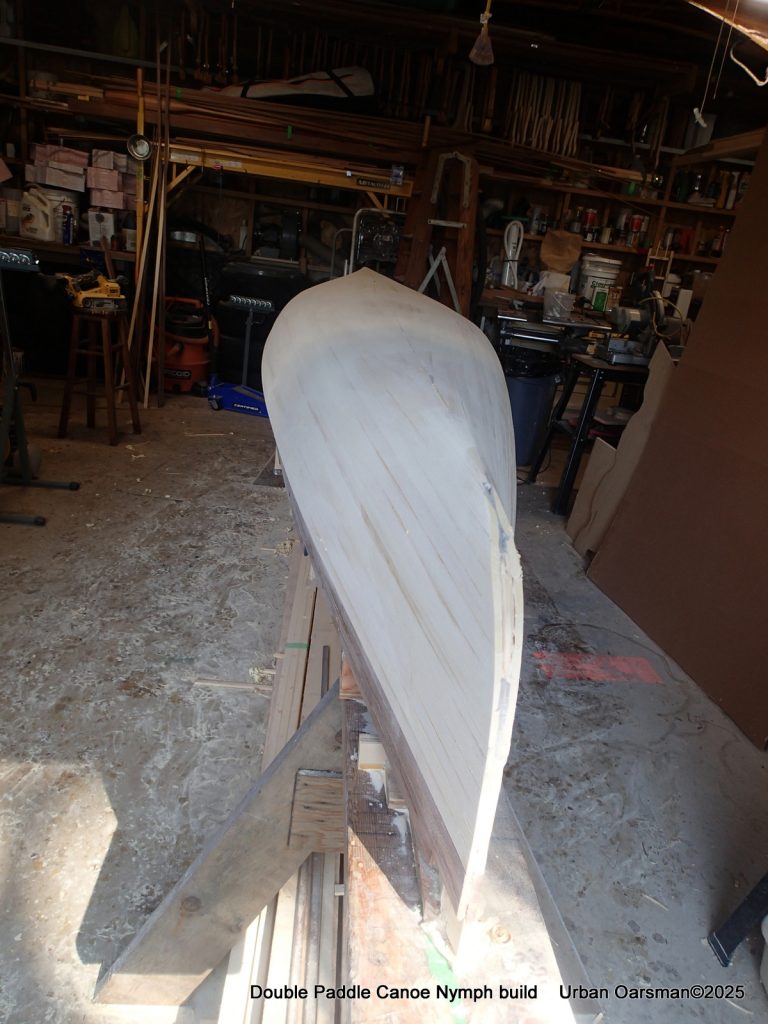
You sure can spend a lot of time sanding…and I did.
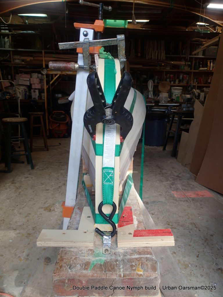
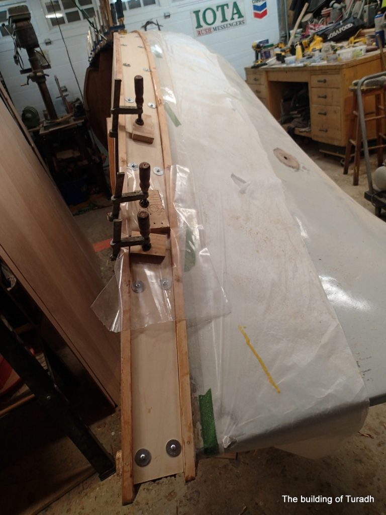
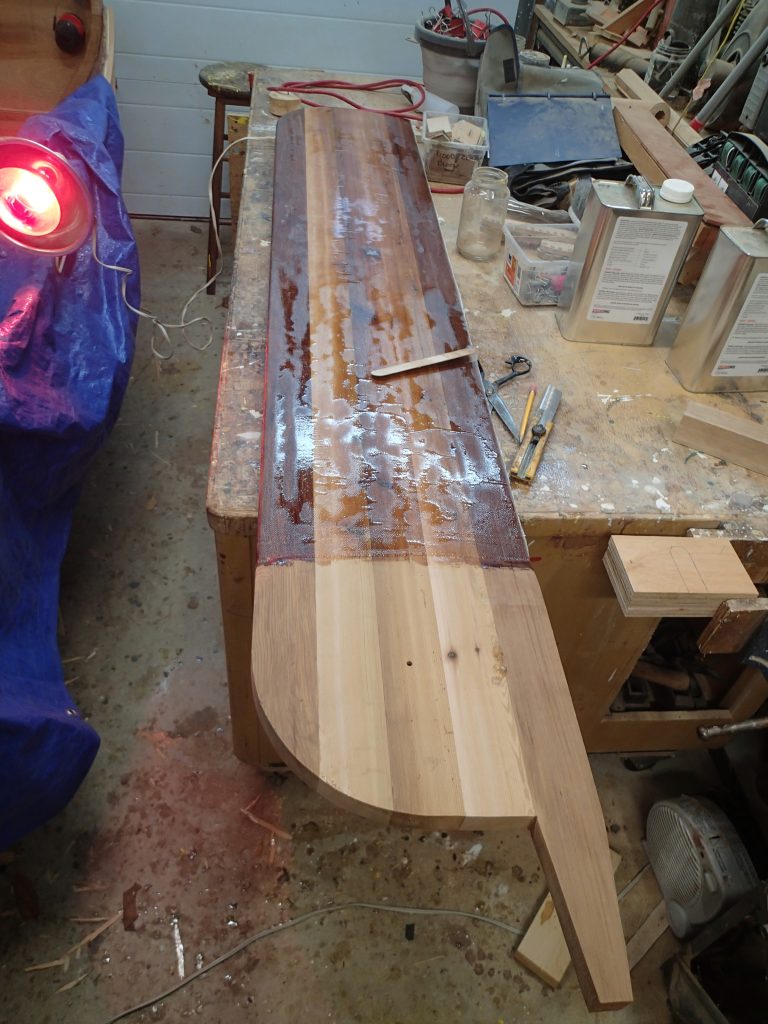
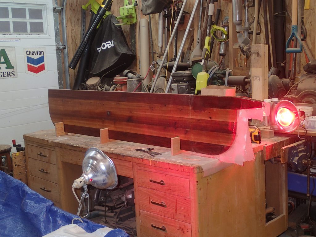
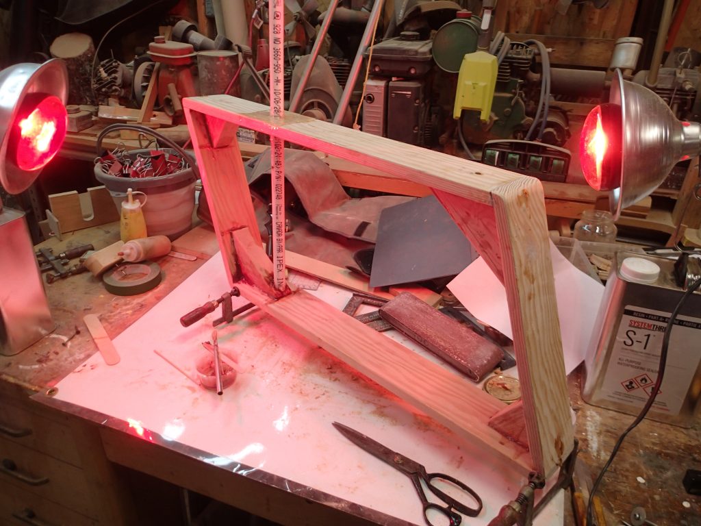
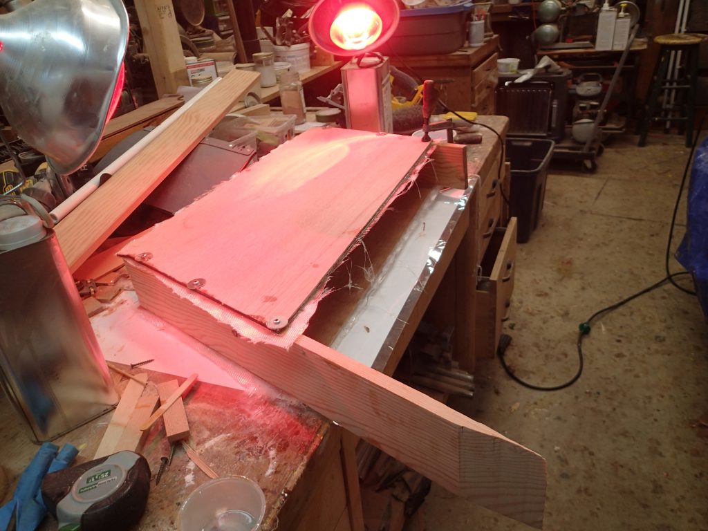
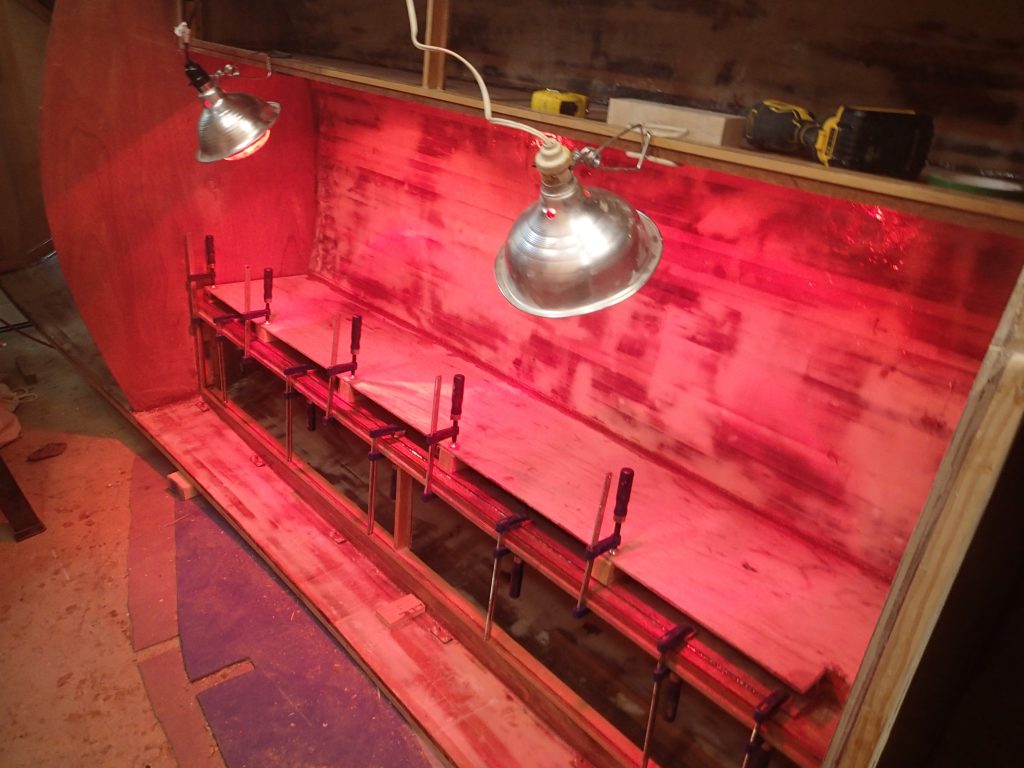
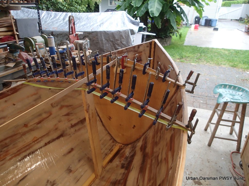
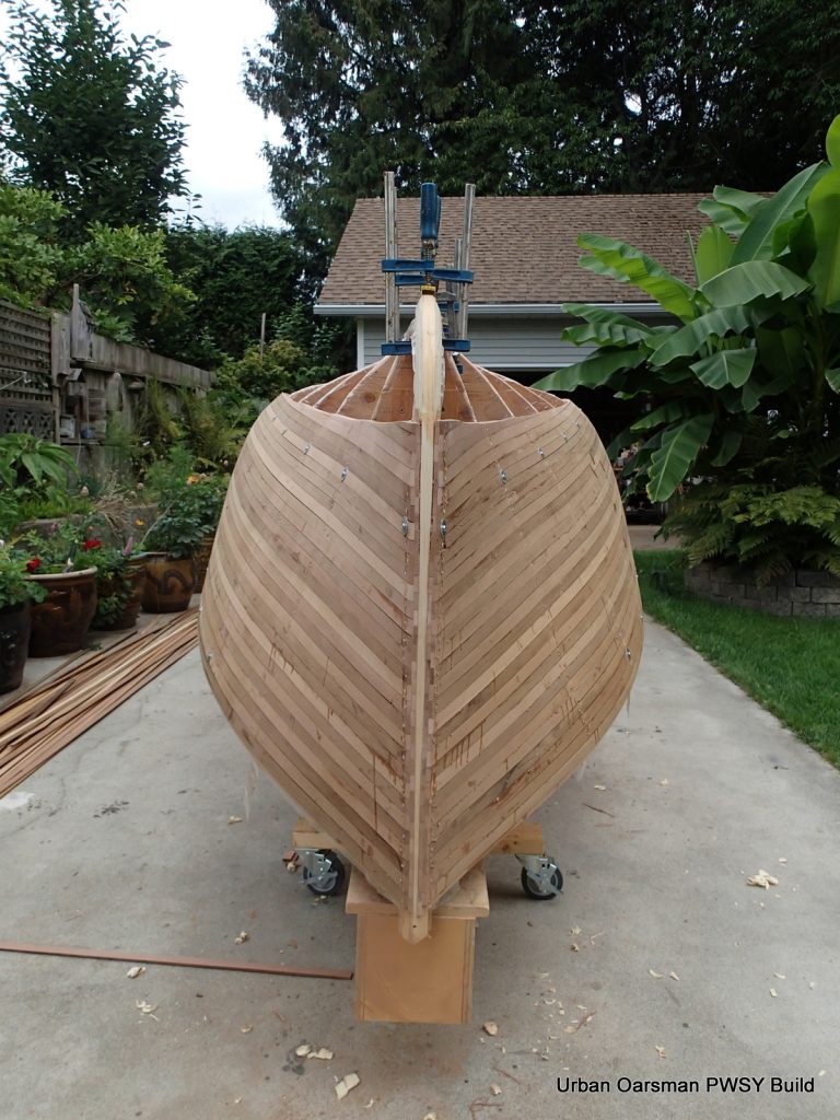
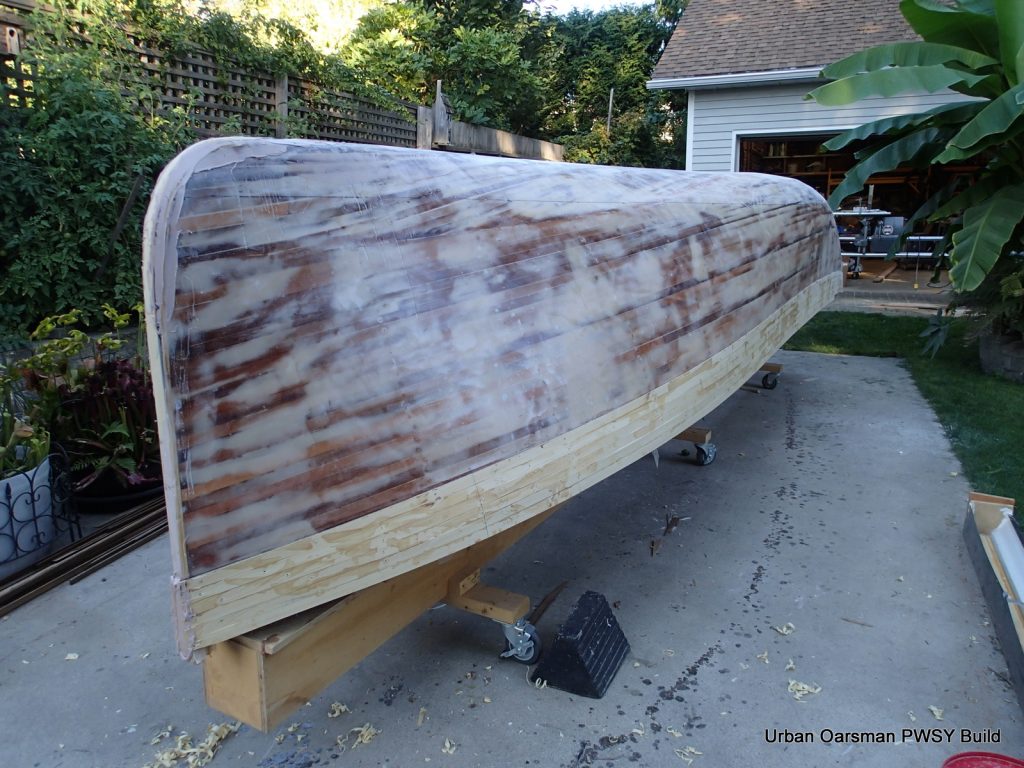
I modified my strong back for this part. To apply clamping pressure, I used ratchet straps to clamp the laminations to the stems. I also screwed in two pieces of scrap plywood to help keep the laminations aligned. Just to be sure, I threw in a long bar clamp where needed.
I got good squeeze-out. Towels help keep the cedar from denting and the straps from moving.
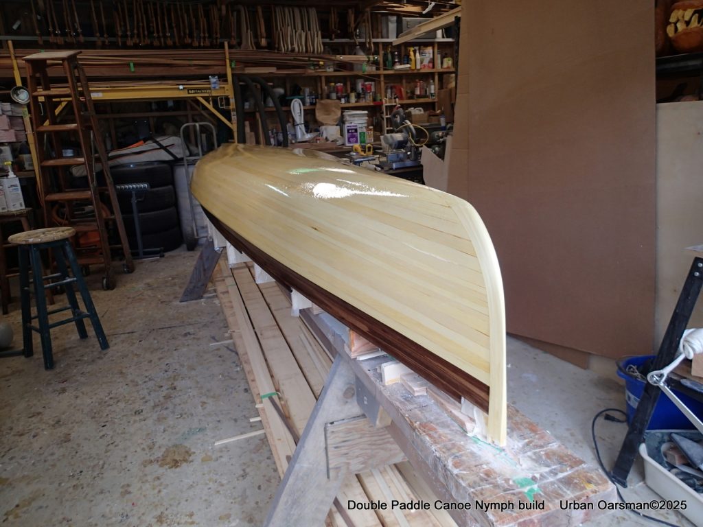
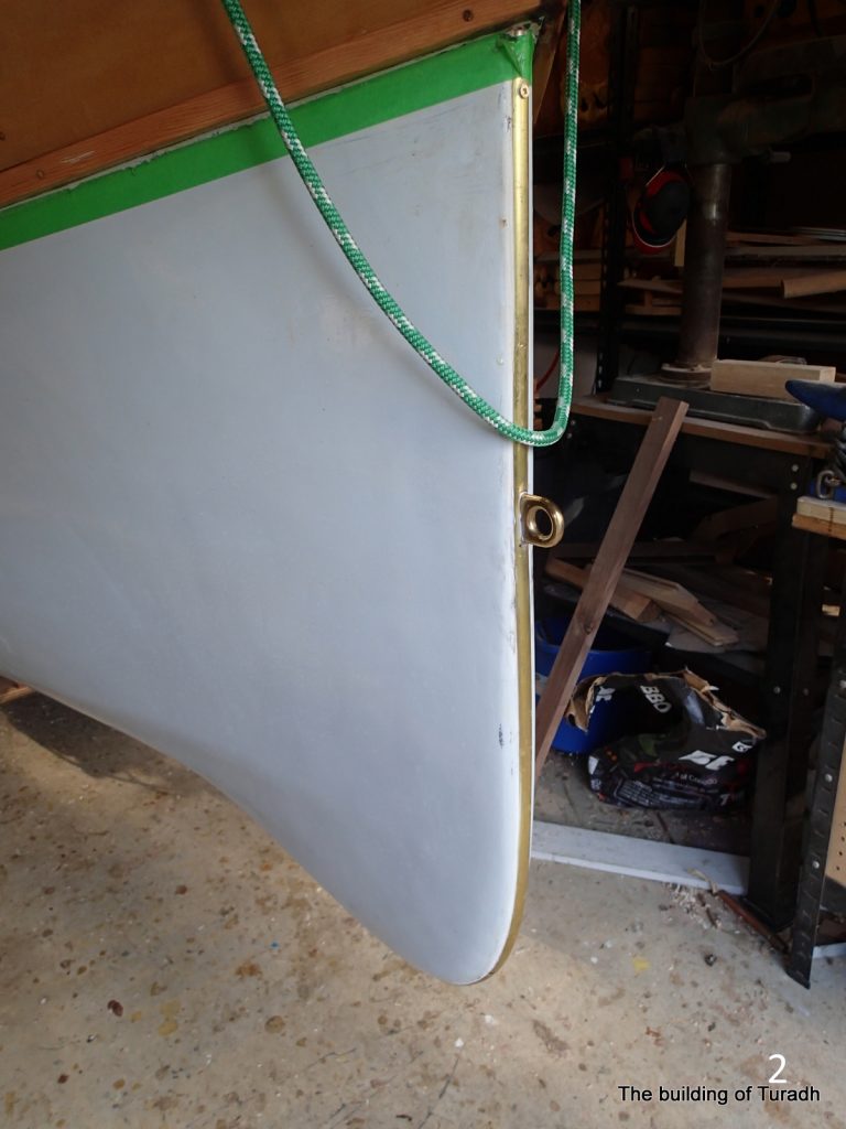
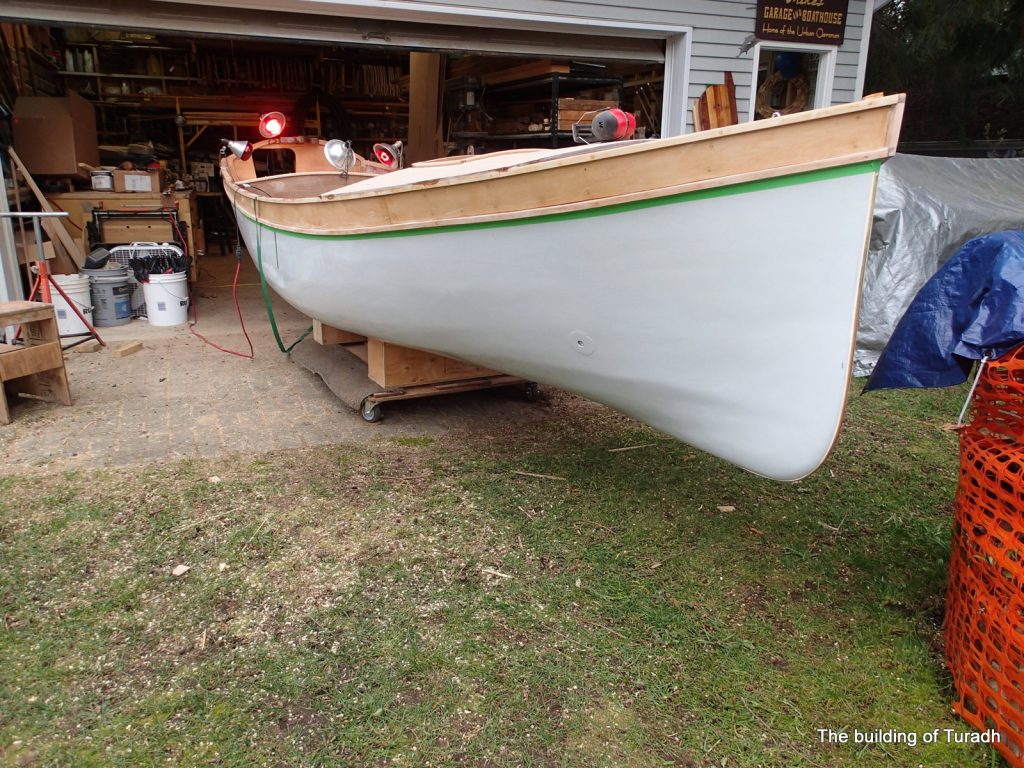
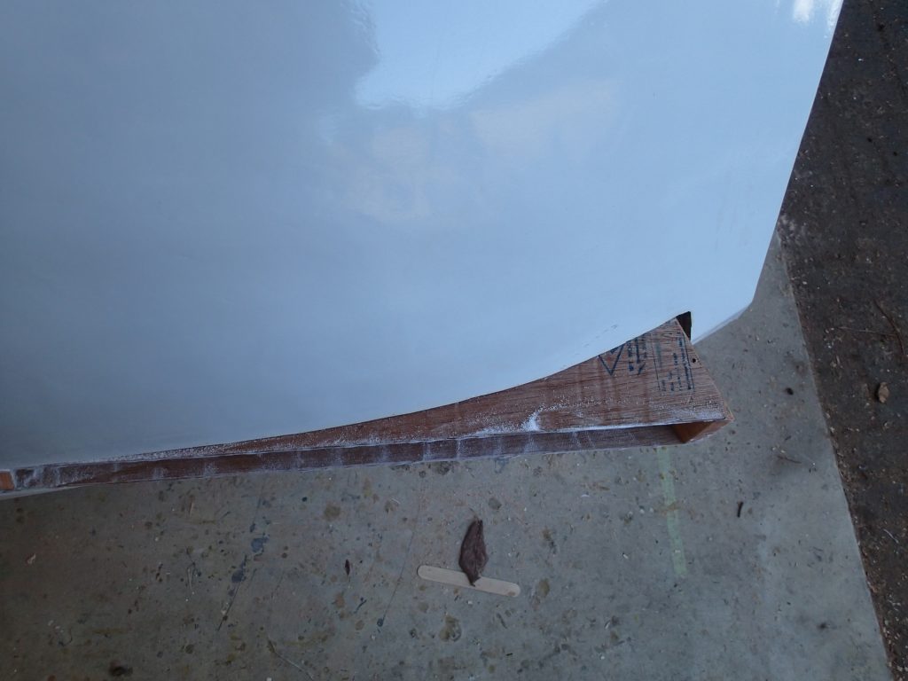
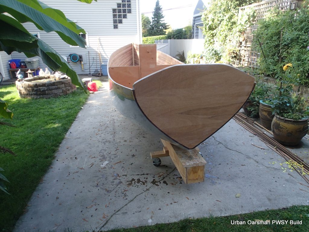
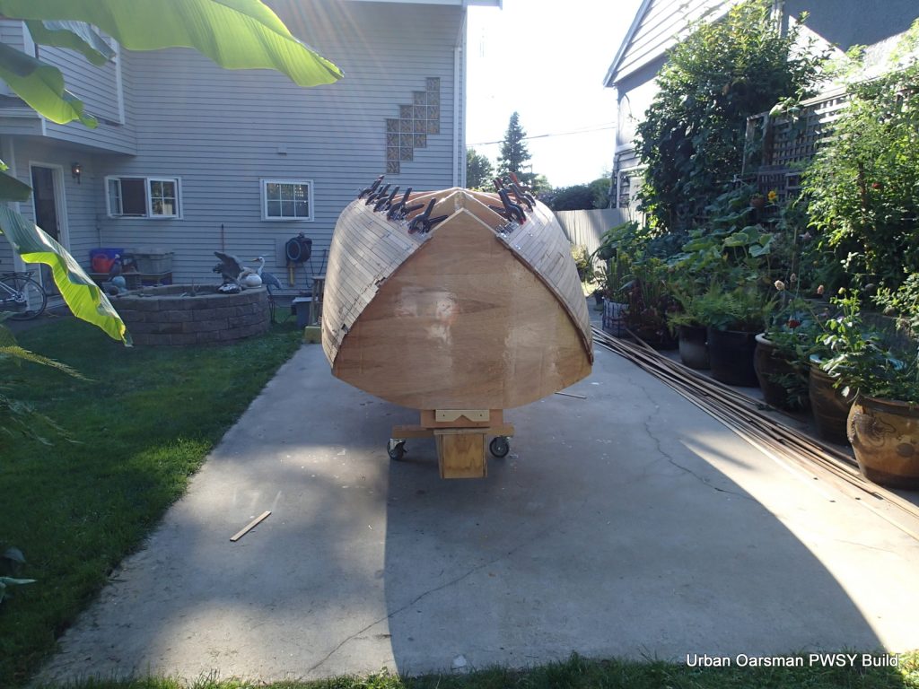
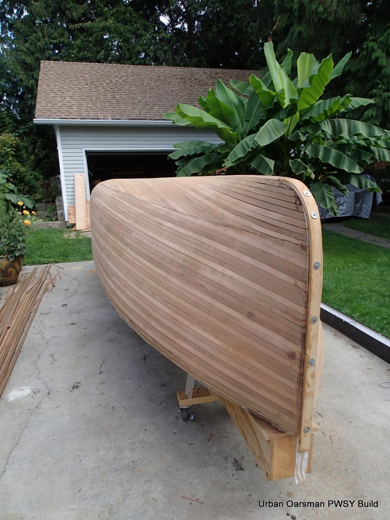
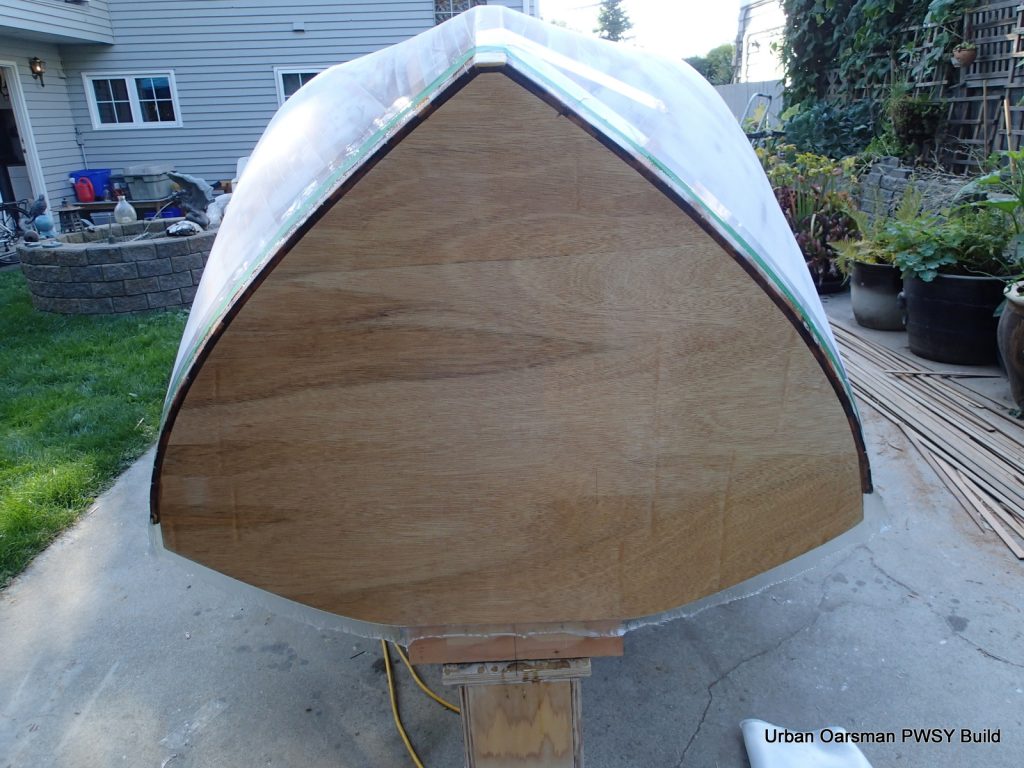
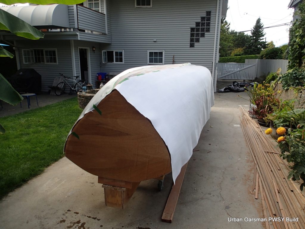
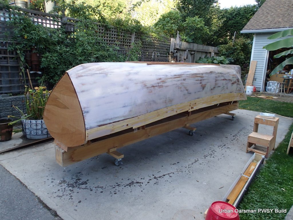
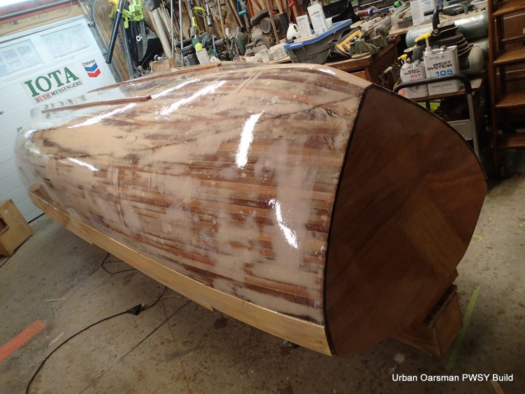
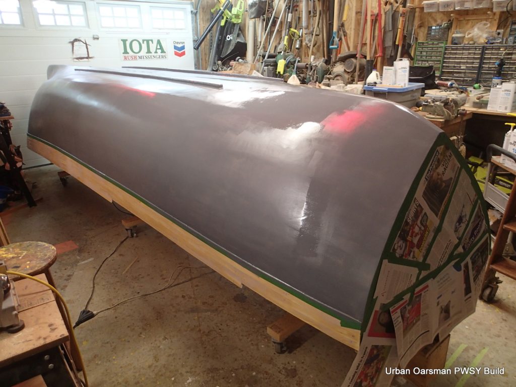
I do not have any photos of the shaping of the outer stem pieces. You can see that I tapered them into the canoe bottom and do not have a keel. I have not yet trimmed the gunnels to shape. I have put 4oz. cloth and three coats of epoxy onto the outside of the hull.
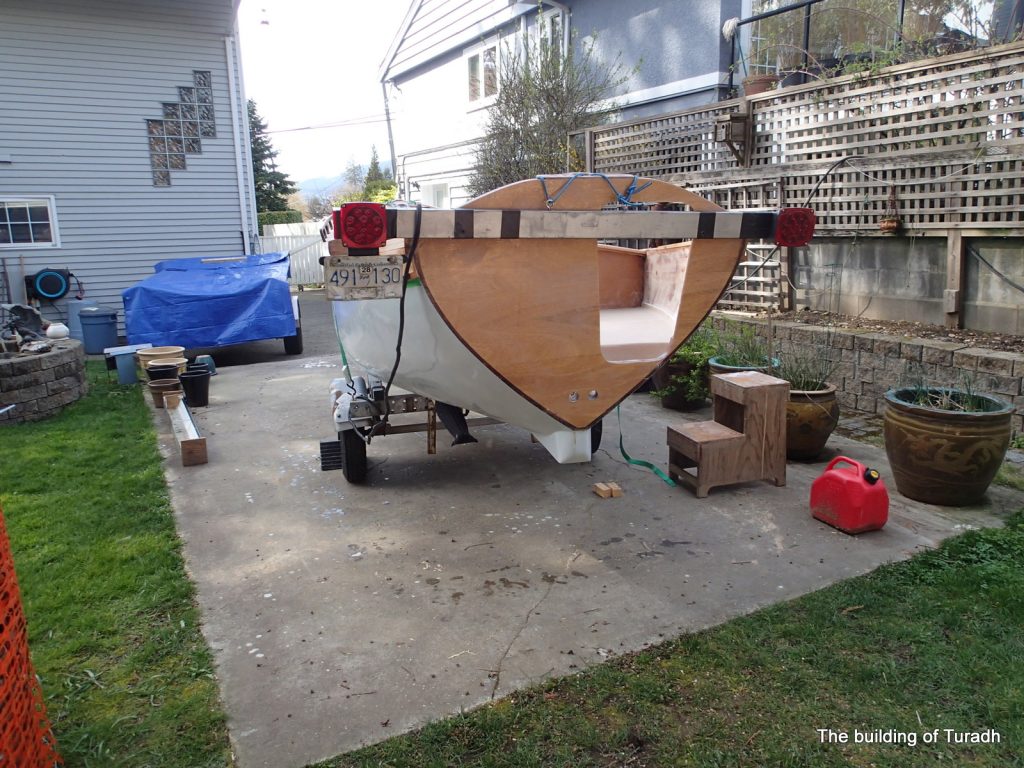
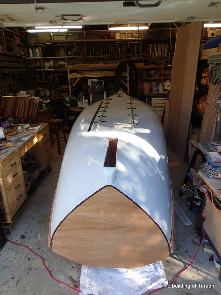
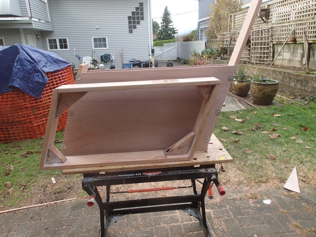
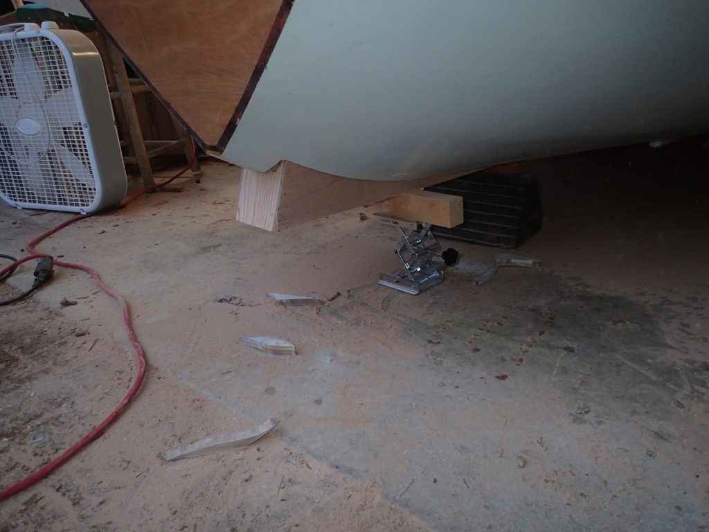
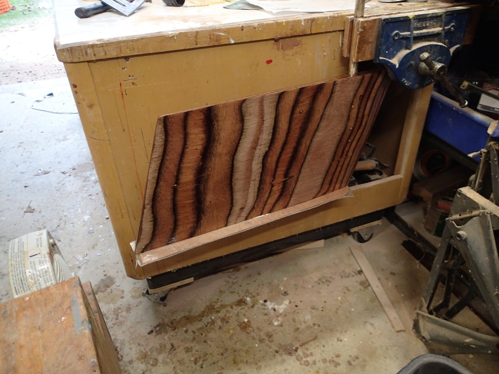
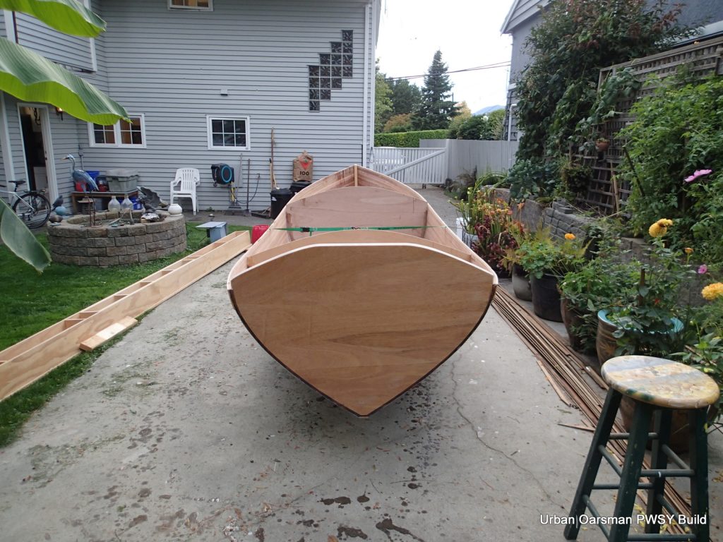
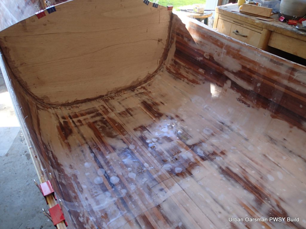
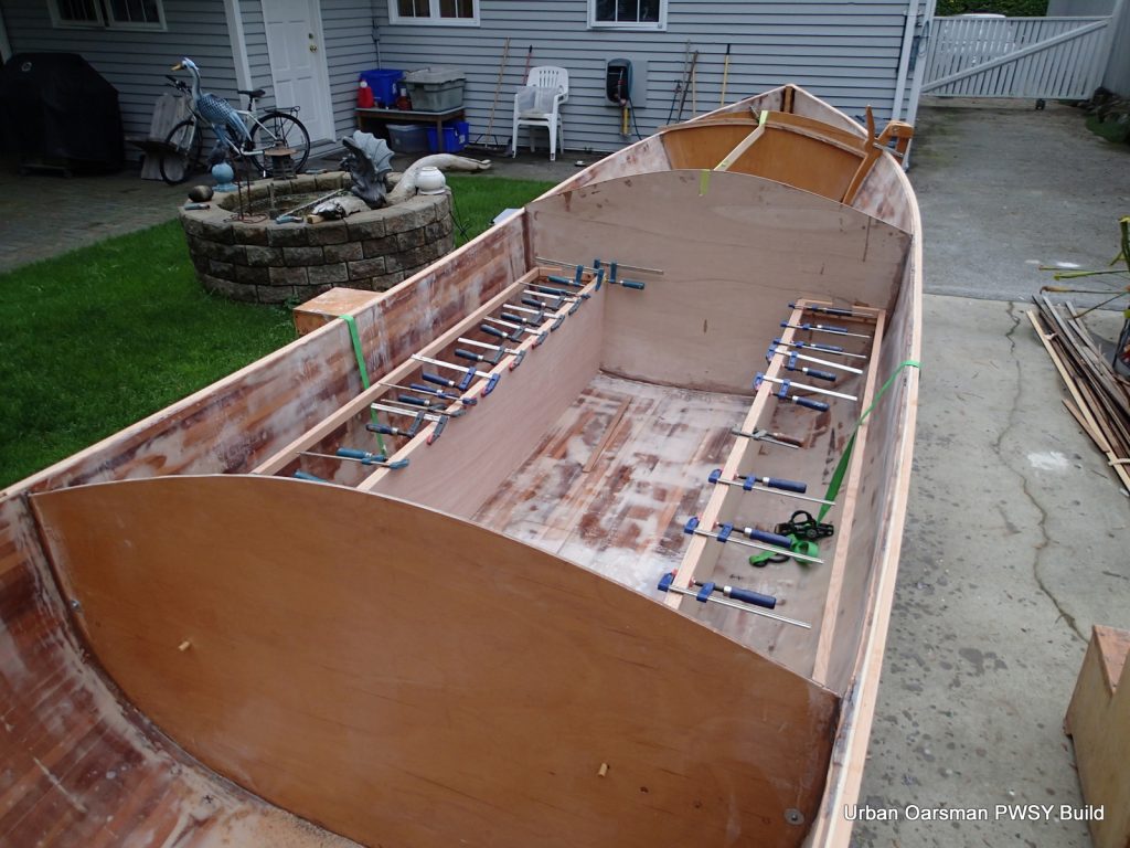
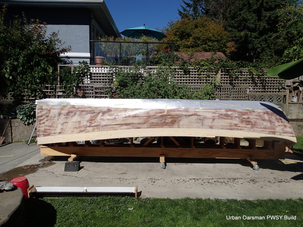
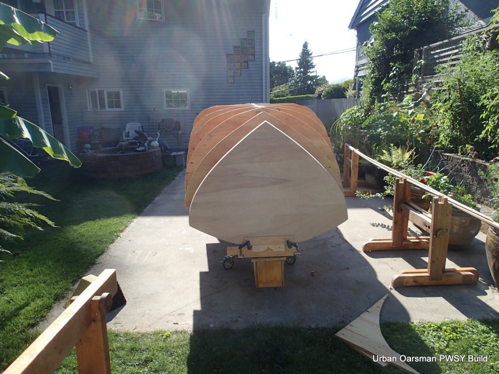
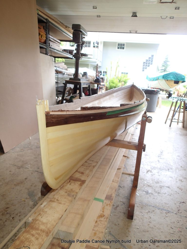
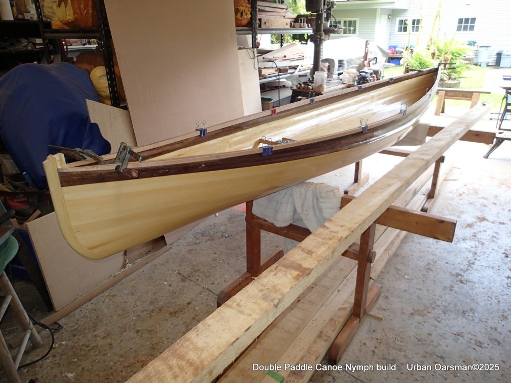
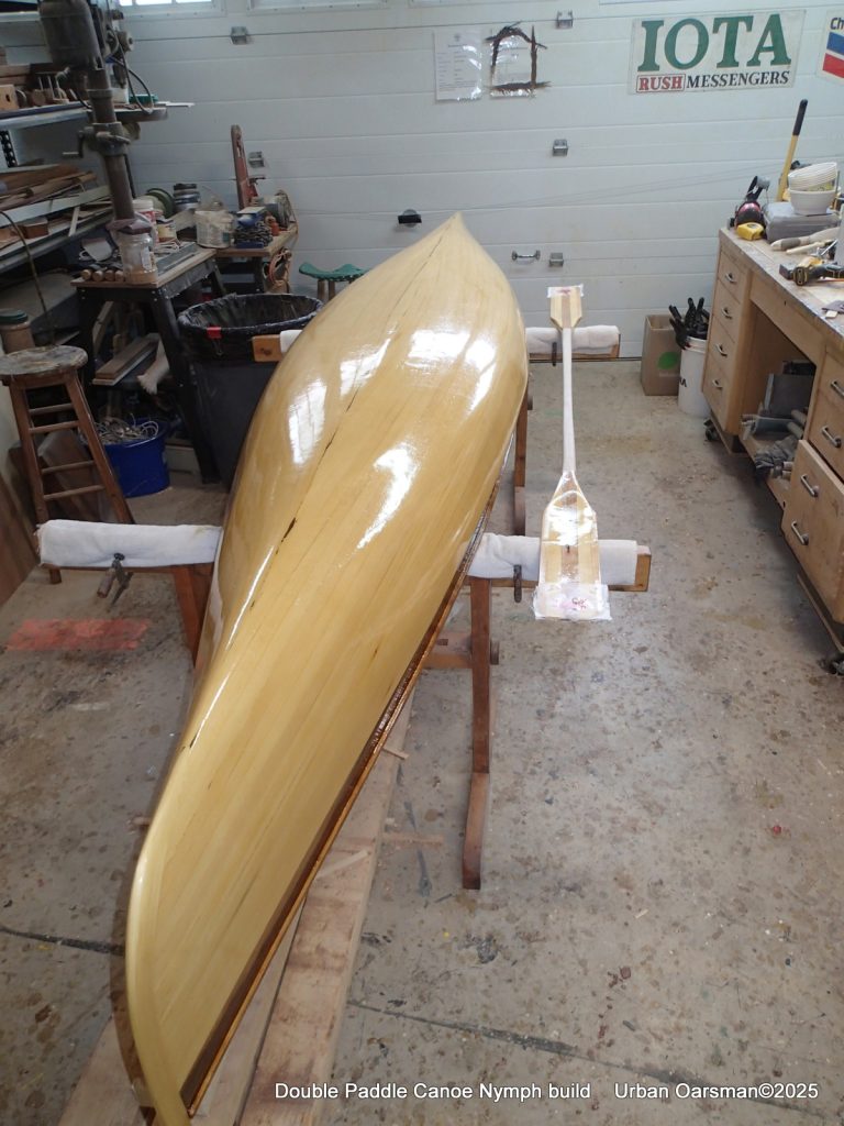
With the outside of the hull all epoxy & clothed up, I can take her off of the forms and the strongback. You can see that the sides have not been shaped. I will do that after the gunnels are on.
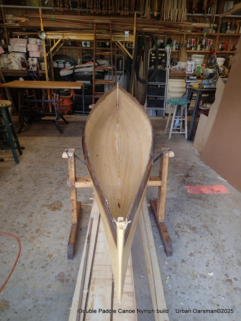
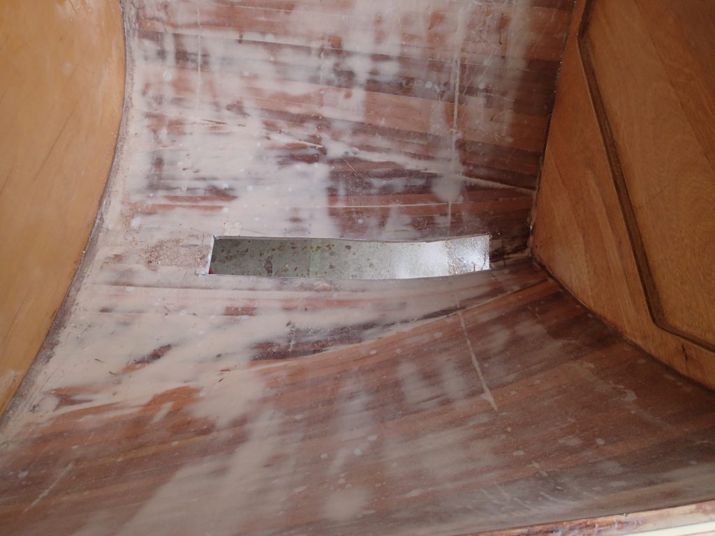
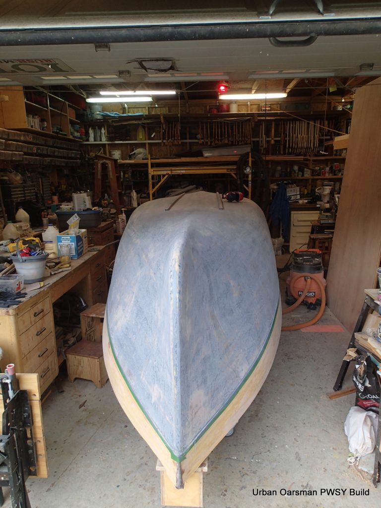
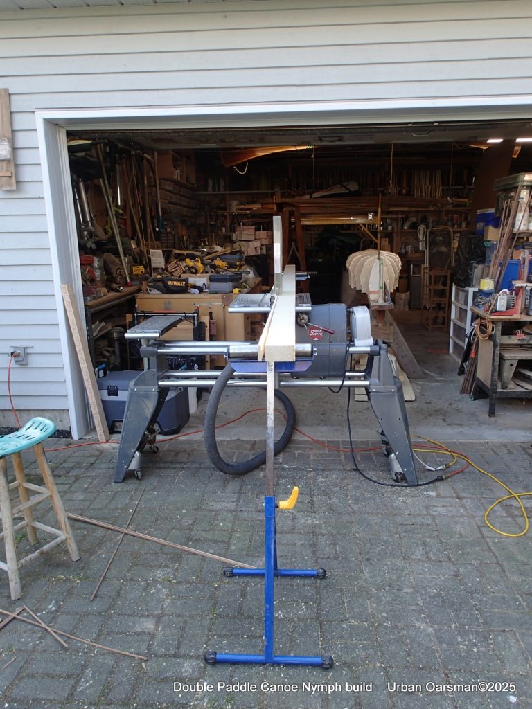
The strongback is put away. The inside still needs to be finished. A lot more of awkward sanding has to be done. (Sigh!)
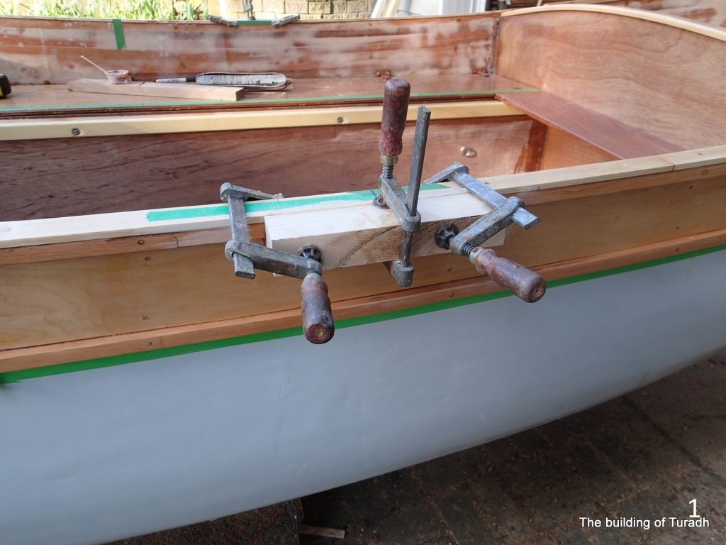
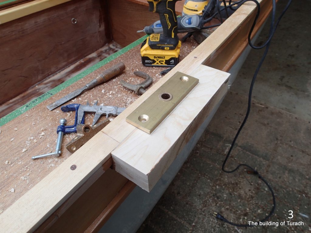
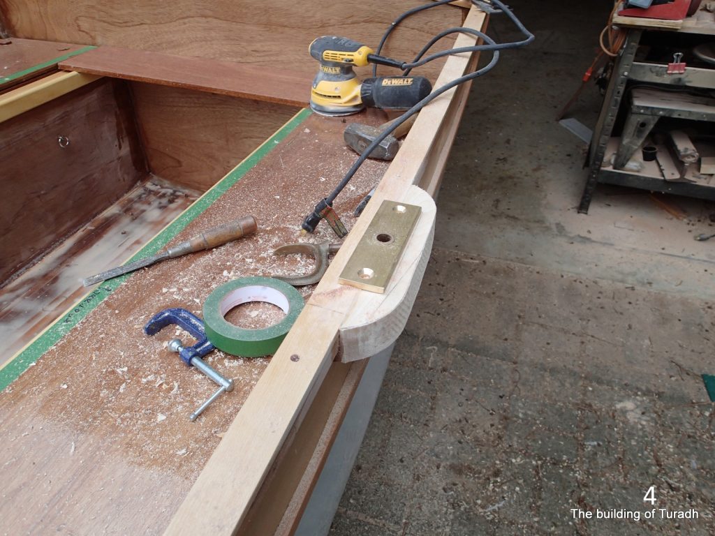
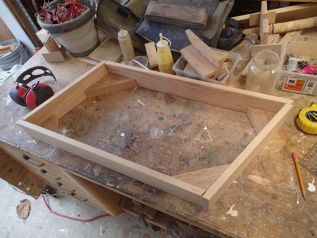
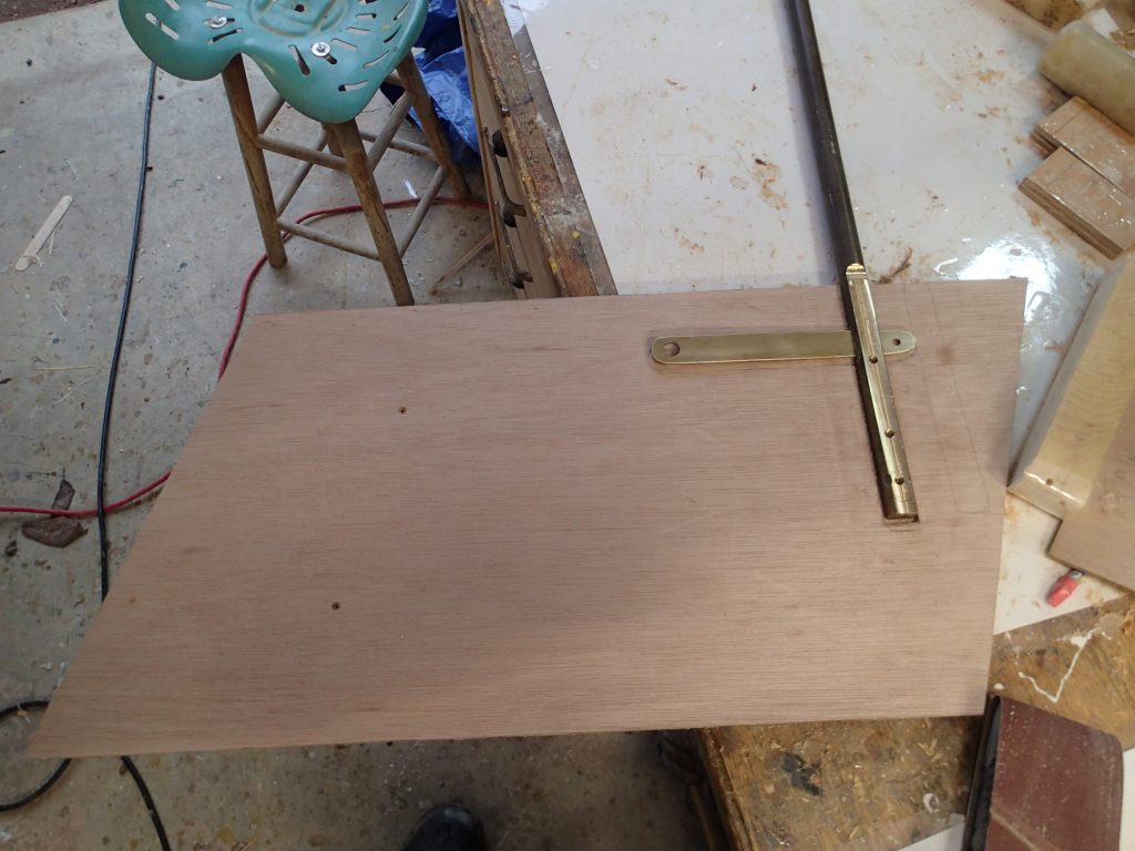
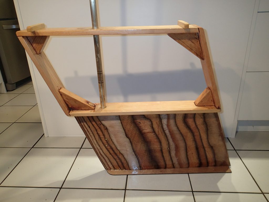
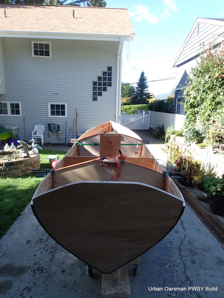
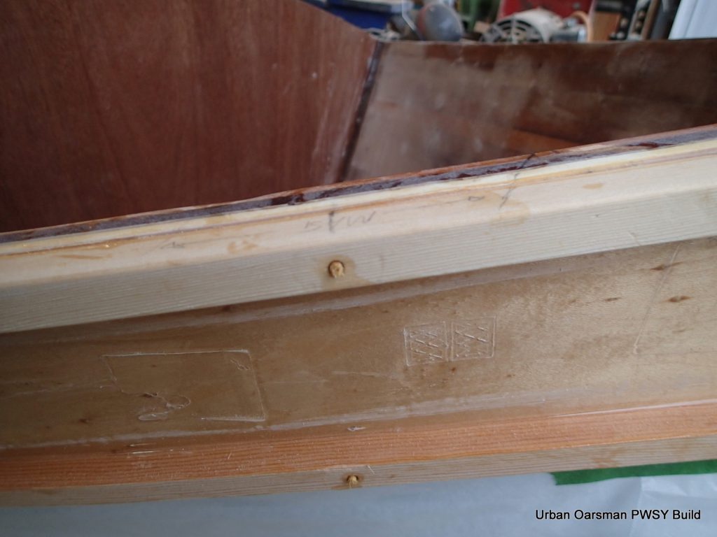
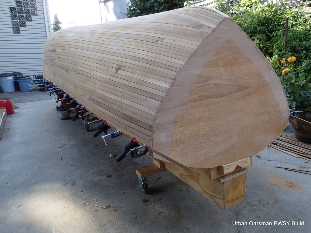
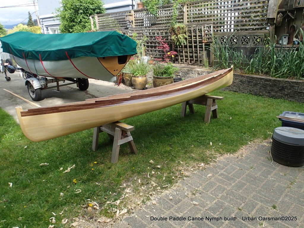
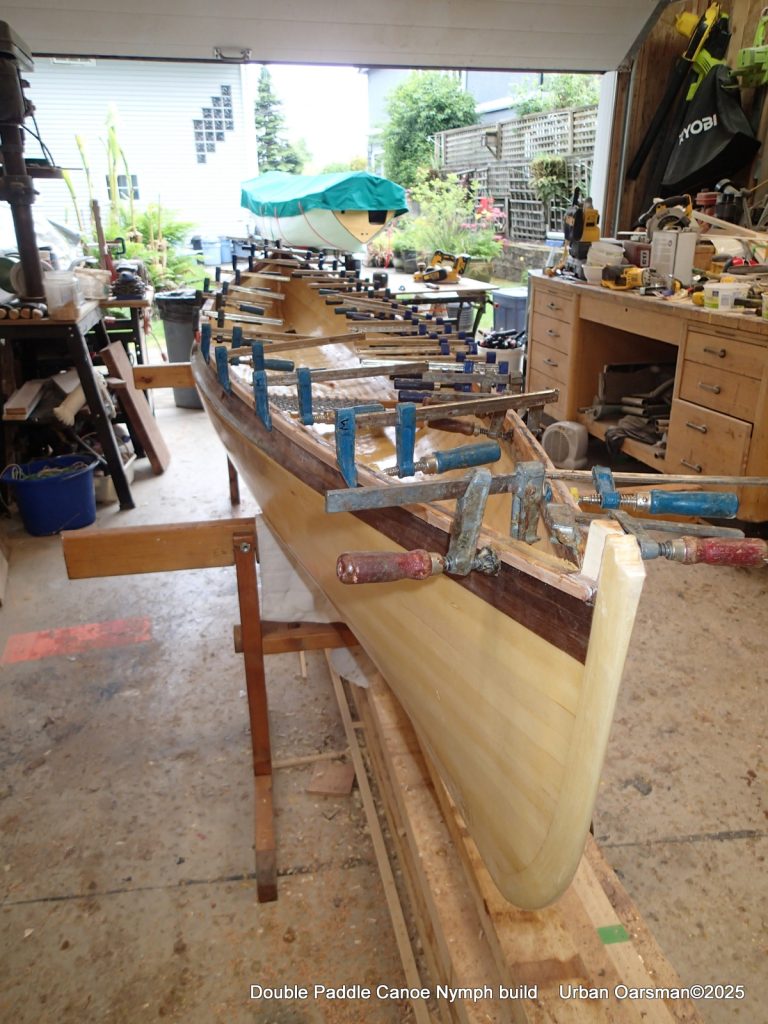
Test fitting the outer gunnels. Form #0 will keep the outer gunnels from distorting the hull shape. The ash gunnels need to be shaped and tapered. To do this, I have one gunnel proud at the bow and the other proud at the stern so I can fit both at the same time. Helps to keep things the same. My tapering jig and procedure is outlined below, in the fitting the inside gunnel part.
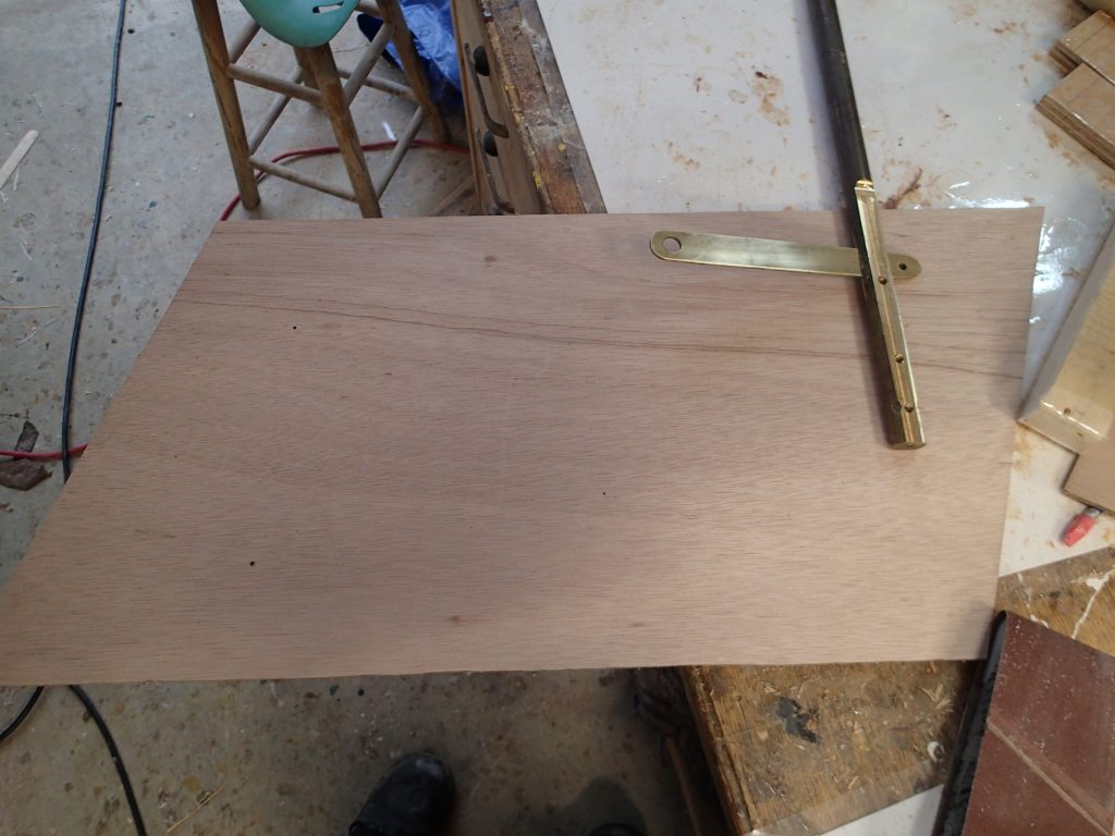
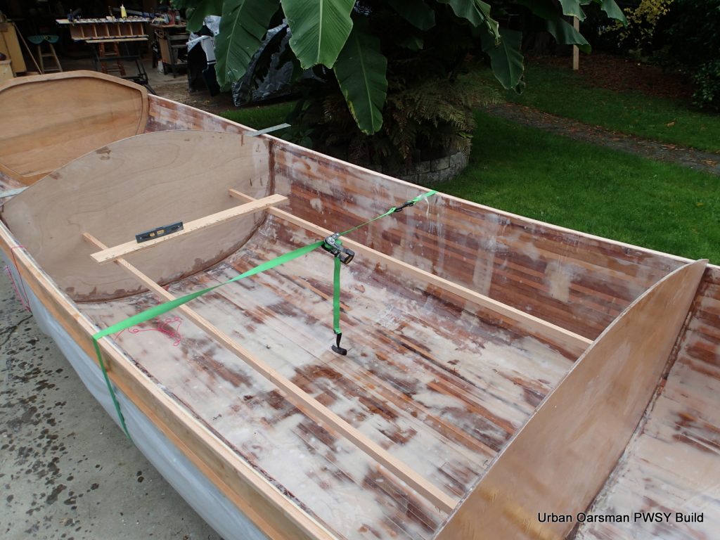
I have tapered and shaped the gunnels. The hull has been leveled so that I can insure that both gunnels, Port and Starboard, are at the same height.
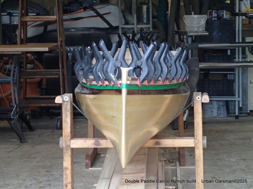
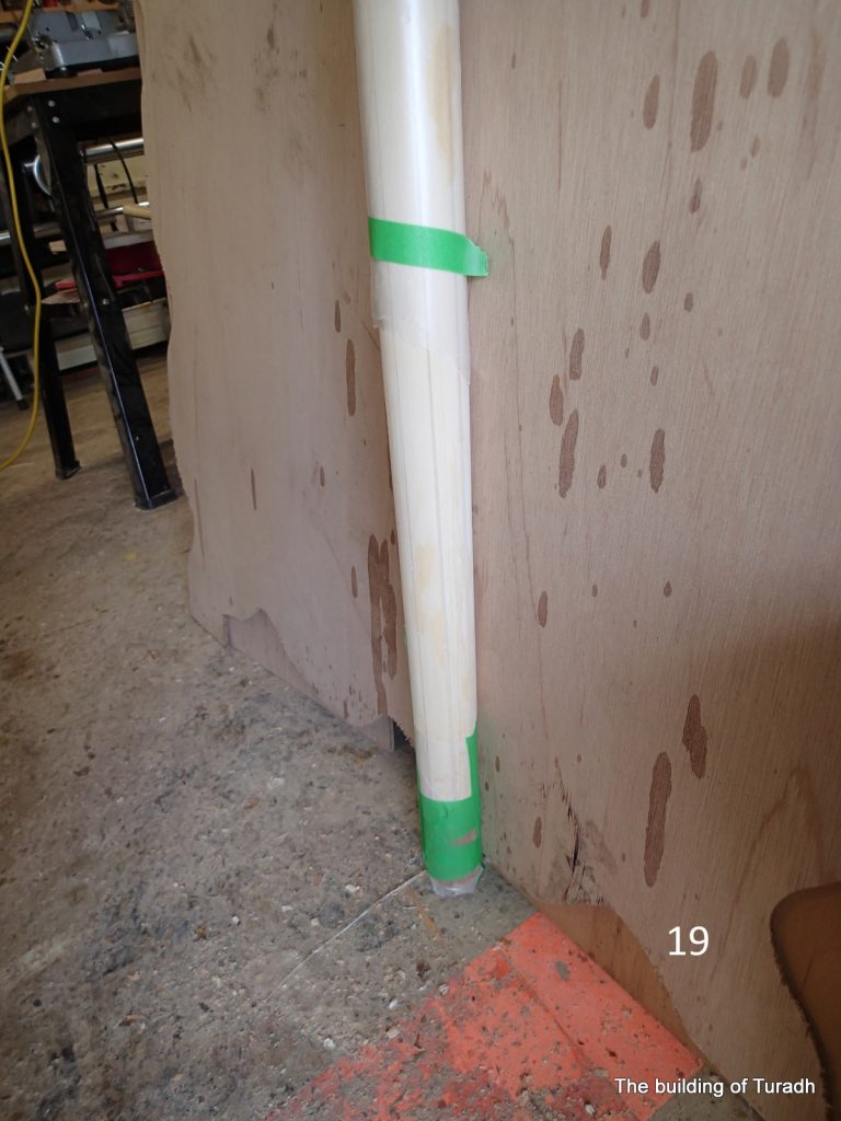
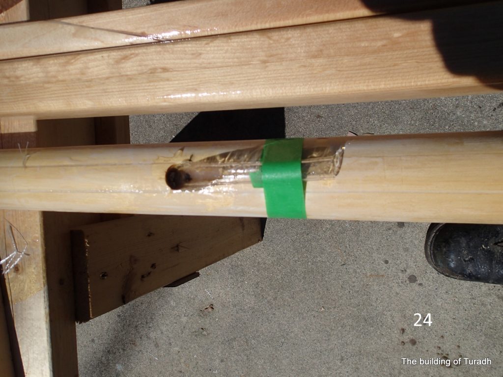
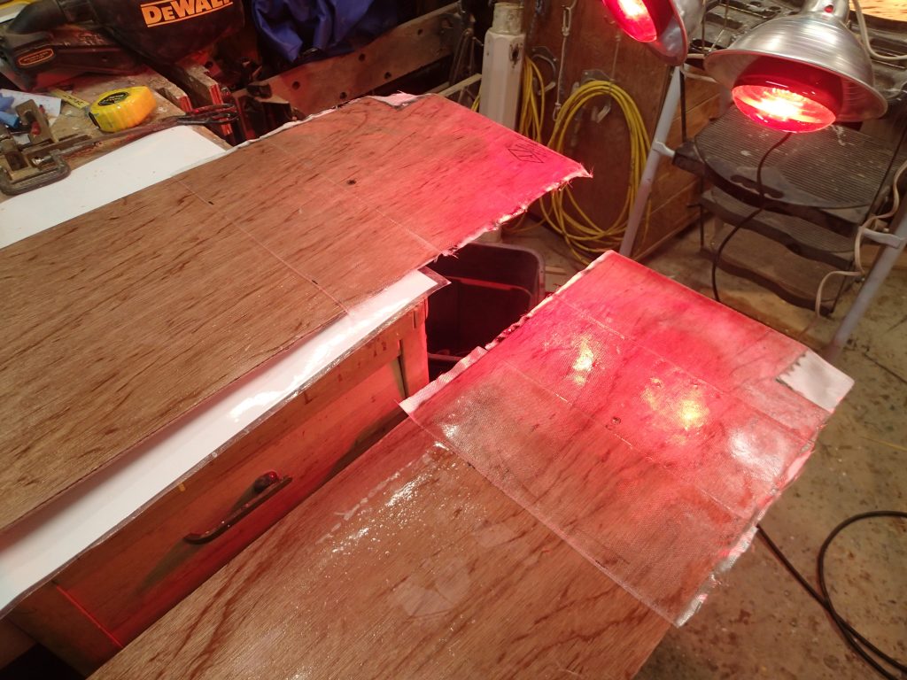
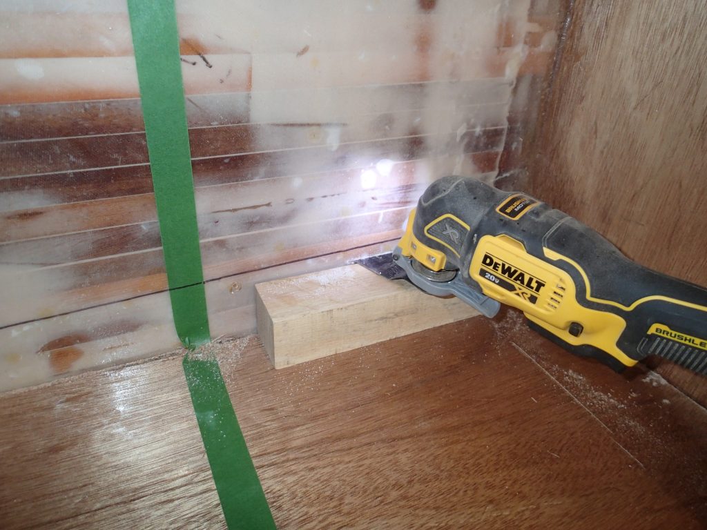
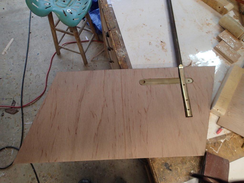
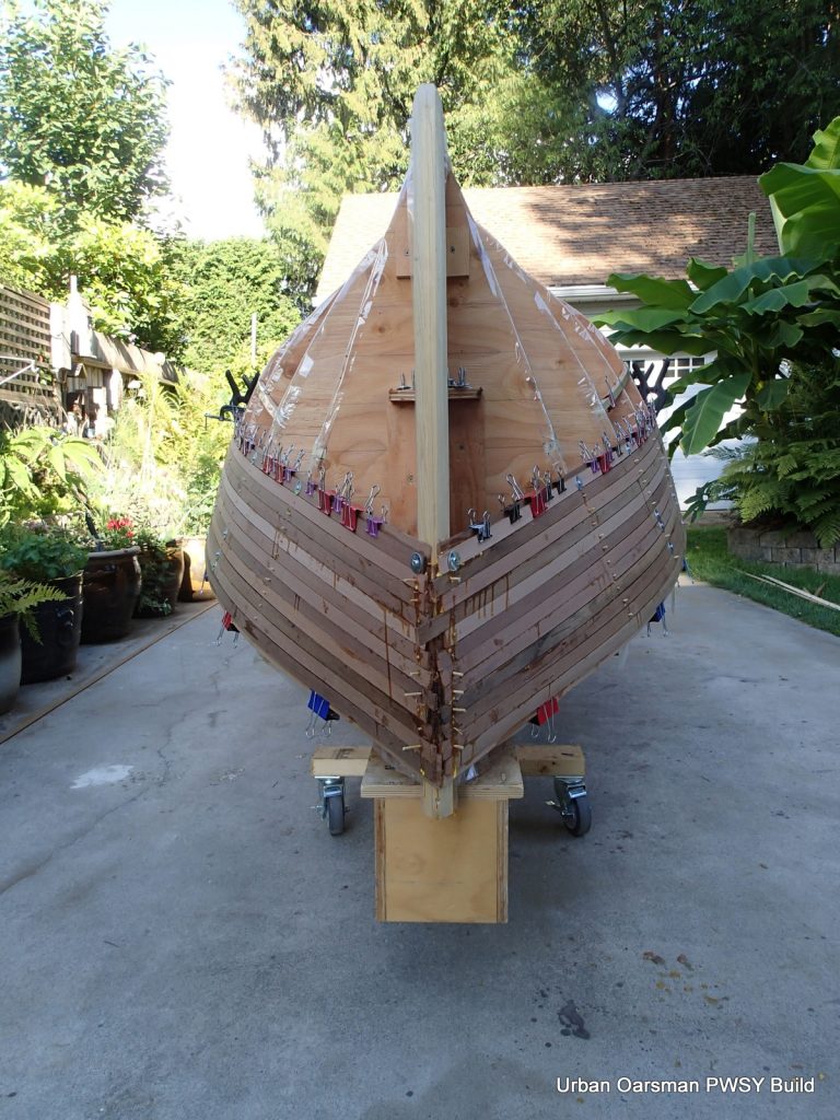
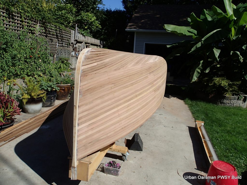
The green tape does two things. I helps aline the gunnels and it also helps with epoxy drips. You can really see the tumblehome shape in this photo.
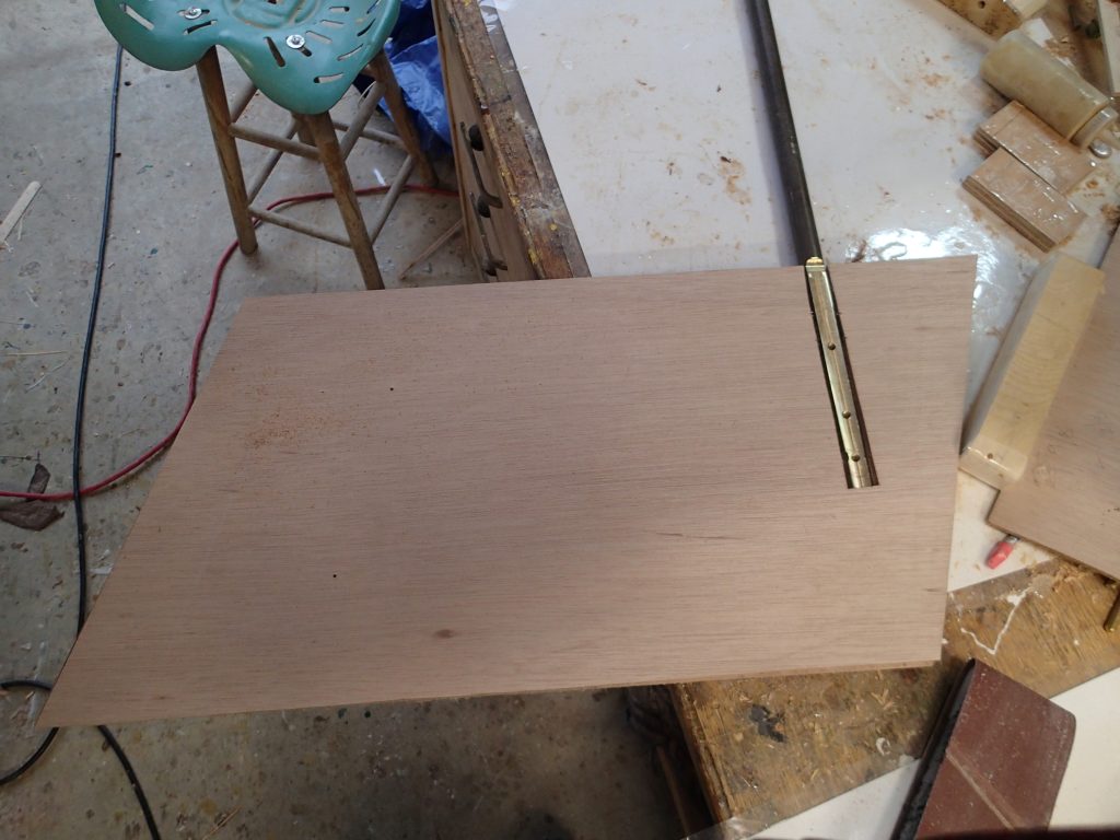
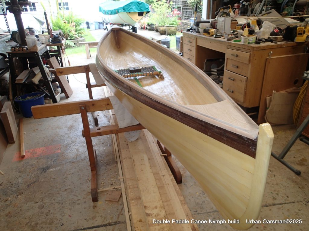
The epoxy has cured and the next steps are to cut the walnut strips to align with the outer gunnels. Oh, and remove the green painter’s tape. Prep the inside for epoxy and cloth.
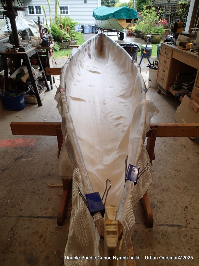
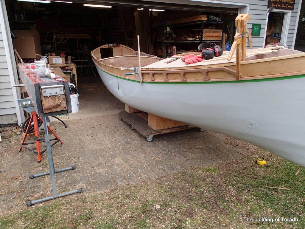
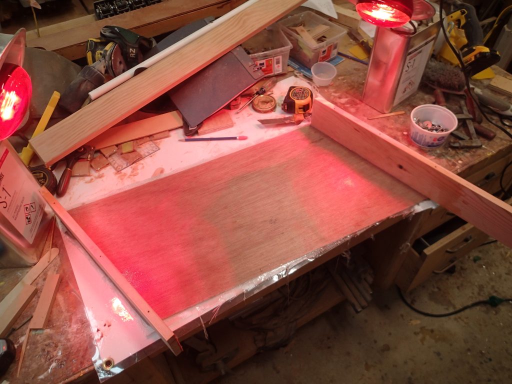
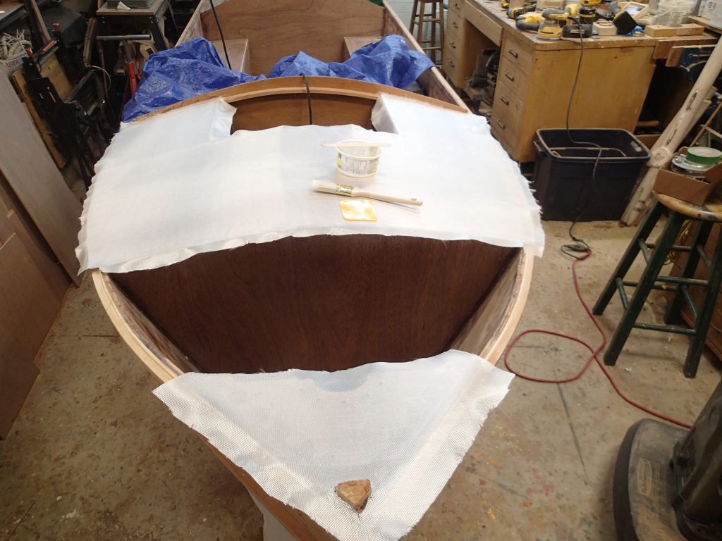
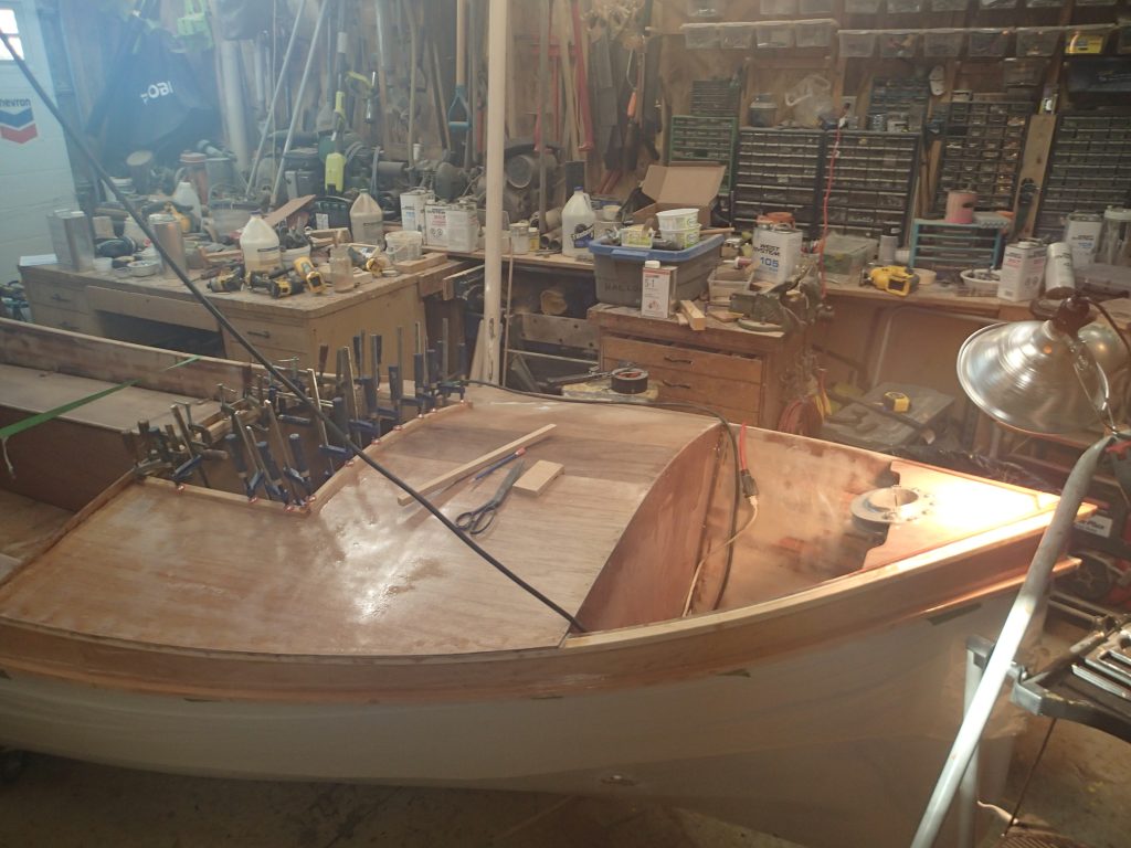
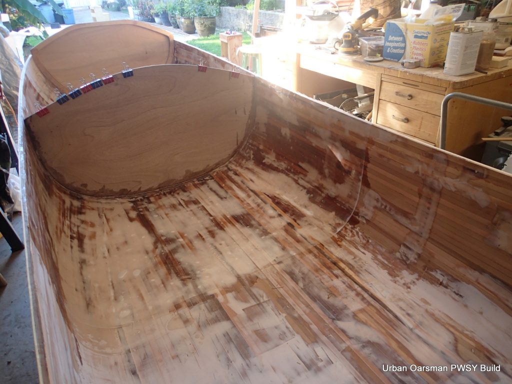
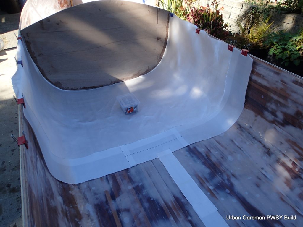
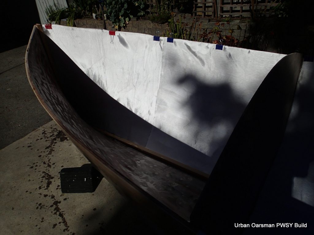
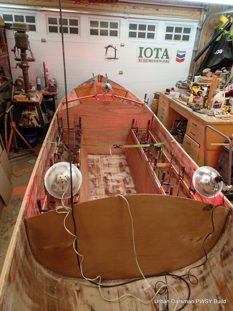
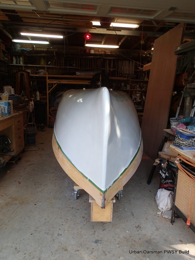
For a more stable work site, I took her off of the straps and put her on the solid wood sawhorse pieces. This way I can actually tie, strap, screw things to the sawhorses if I need to. I am using 4oz. cloth to keep the weight down. After the epoxy and cloth are done, I will install the inside gunnels. The 1″ bulldog clamps are really handy here. They are good for up to ¾” clamping thickness.
You can see that I still have to trim the cloth at the gunnel. Towels keep the sawhorses from scratching/denting the hull.
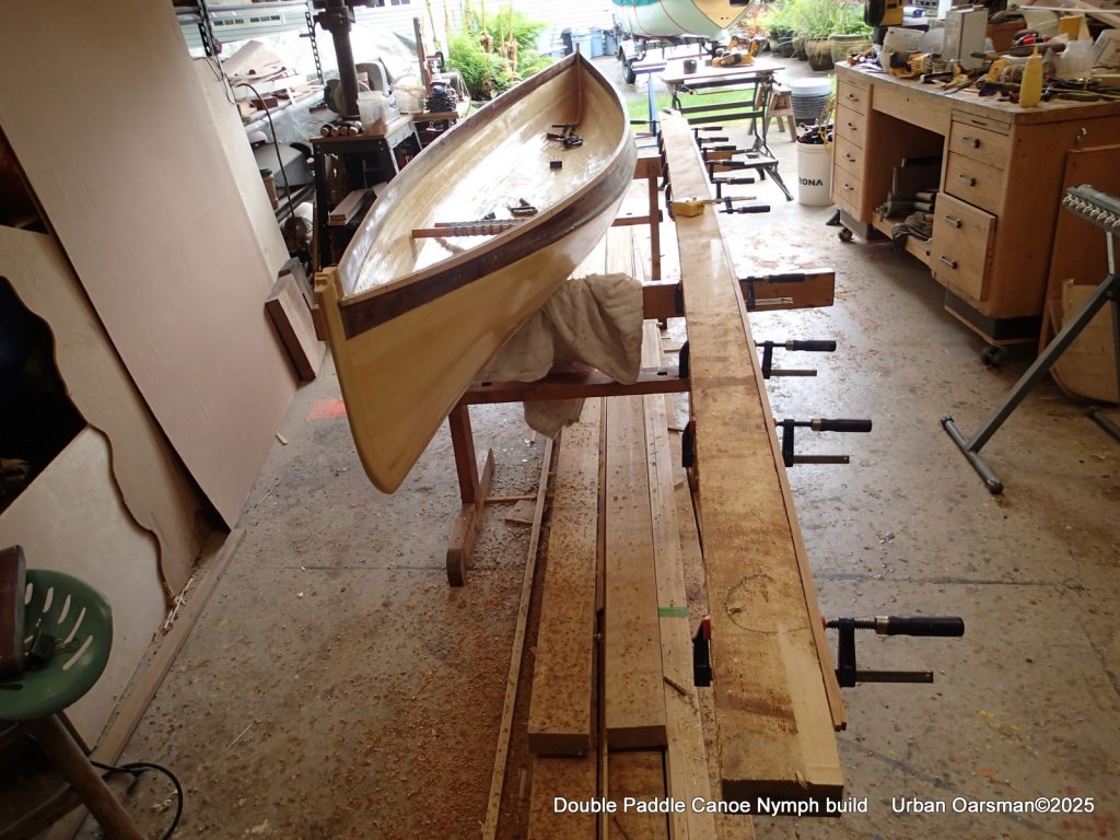
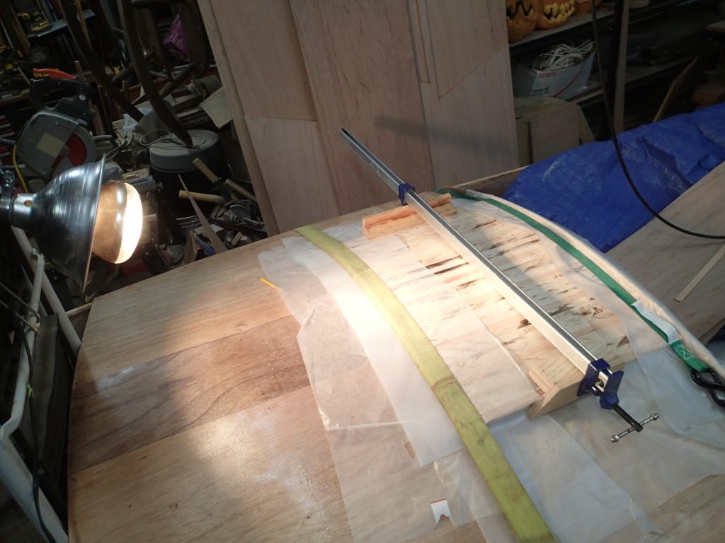
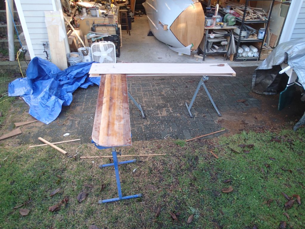
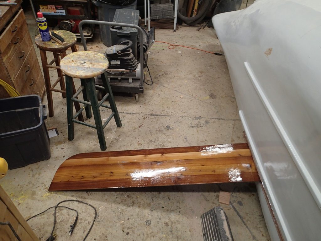
To the right of the hull is the plank that I used to make the gunnel tapers. I used my power planer to plane off 1/16″ every 18″ or so to create a taper. To do this you mark the gunnel every 18″ and create a centre to the strip. starting from the end, you plane 1/16″ off from the 18″ mark to the end of the strip. You then go to the second 18″ mark and plane to the end of the strip. So now you have tapered the strip 1/16″ at the second mark and 1/8″ at the first mark. If you plane from the third 18″ mark, you end up with a taper from the third mark of 1/16″, 1/8′ inch at the second mark and 3/16″ at the first mark. It is sorta like a series of steps you plane out. Please see diagram below:
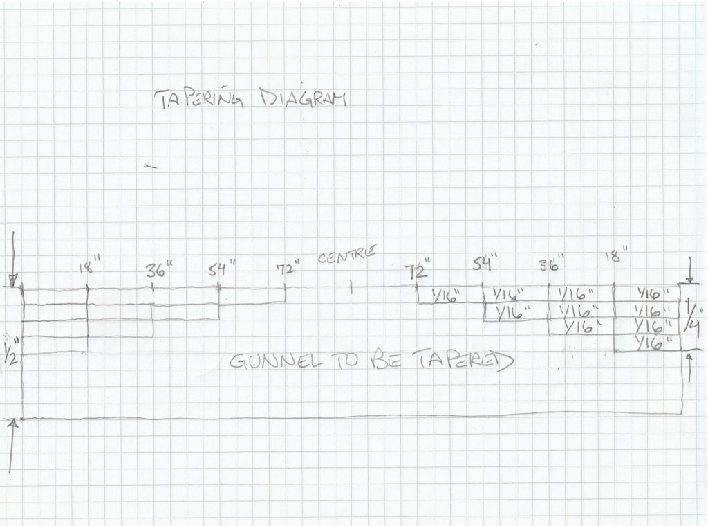
So here I have (not to scale!) my 180″ long by 1/2″ square gunnel that I want to taper to 1/4″ at each end. To get it tapered 1/4″, I can do four 1/16″ passes with the power planer. For an even taper, I divide the tapered part (the 72″ towards the ends) into even lengths (18″ in this case). The first pass starts at the 18″ mark. The second at the 36″ mark, the third at the 54″ mark and the last at the 72″ mark. The end result will be the gunnel piece is 1/4″ less at the 18″ mark, 3/16″ less at the 36″ mark, 1/8″ less at the 54″ mark and 1/16″ less at the 72″ mark. One last shallow (say 1/32″ or 1/64″) pass will even out and “steps” and give you a smooth taper.
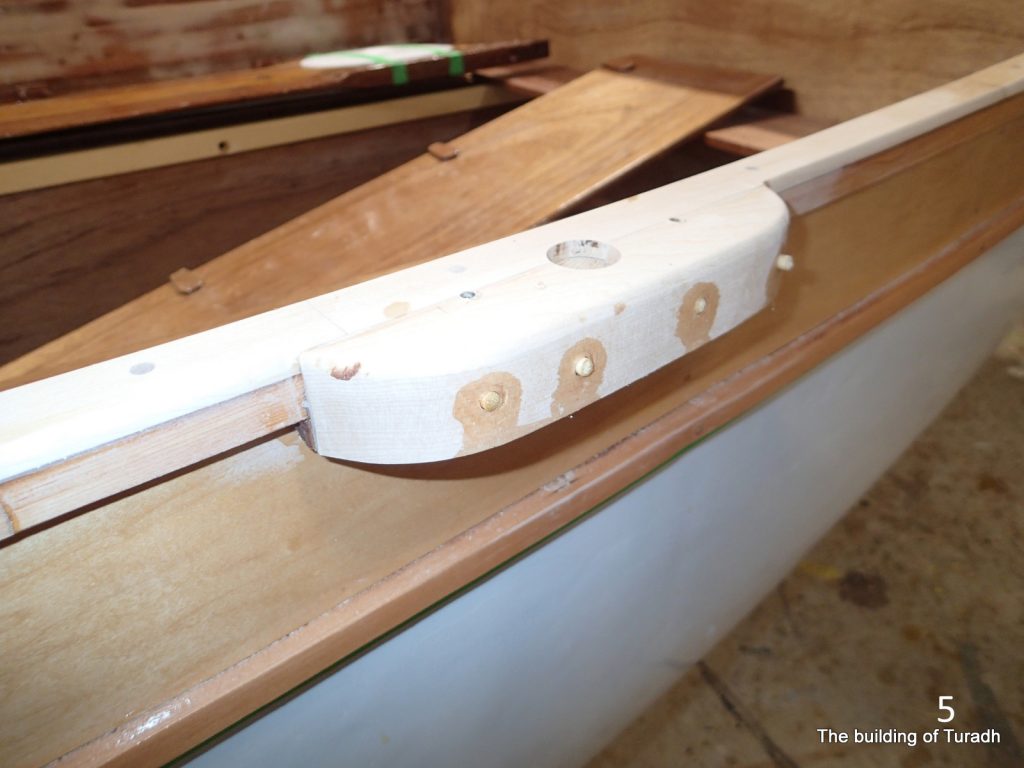
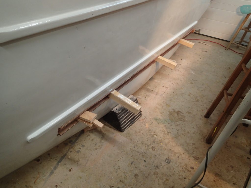
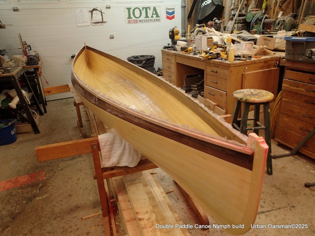
Having tapered both the width and height of the inside gunnels, they are glued in just like the outer gunnels were. The gunnels also get the top and bottom edges profiled so that any water inside the canoe will easily drain out. If the canoe is stored upside down, the outer gunnel is profiled as well for drainage. Any water sitting in your stored canoe is bad.
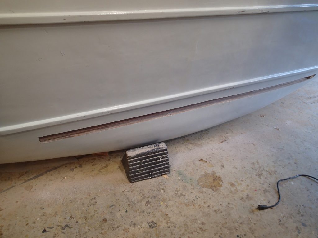
In the above photo the gunnels have not been profiled for water drainage.
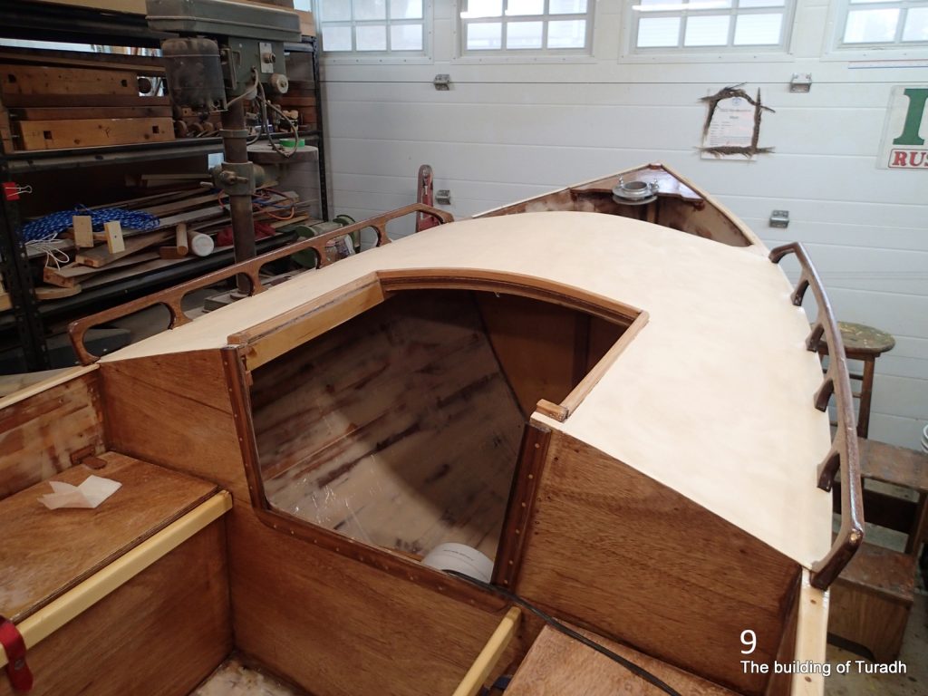
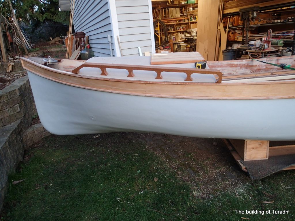
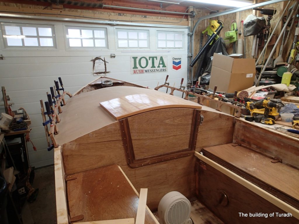
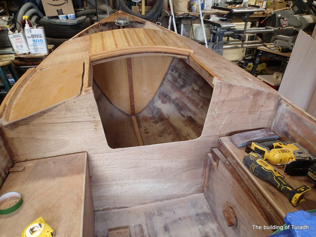
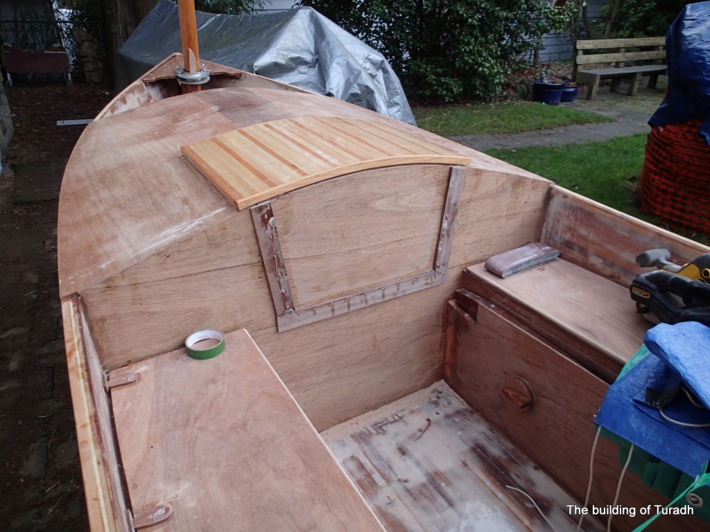
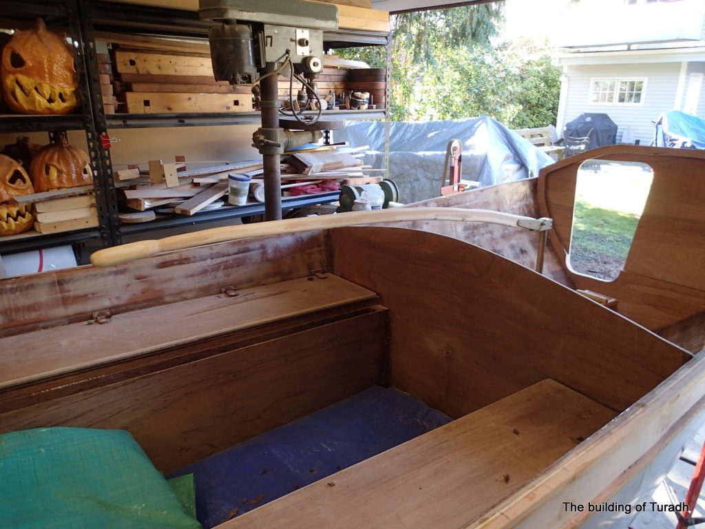
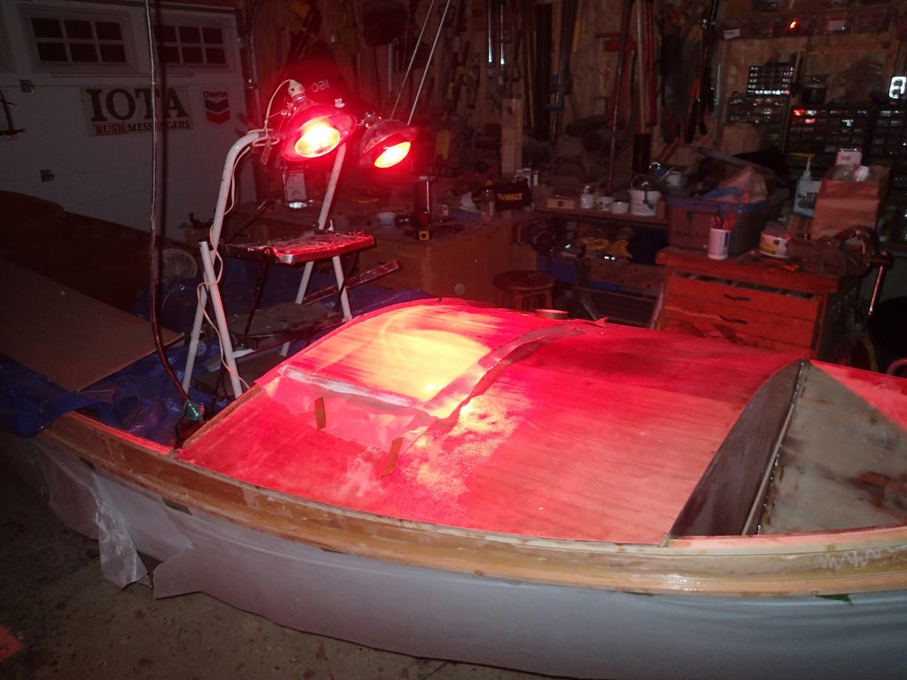
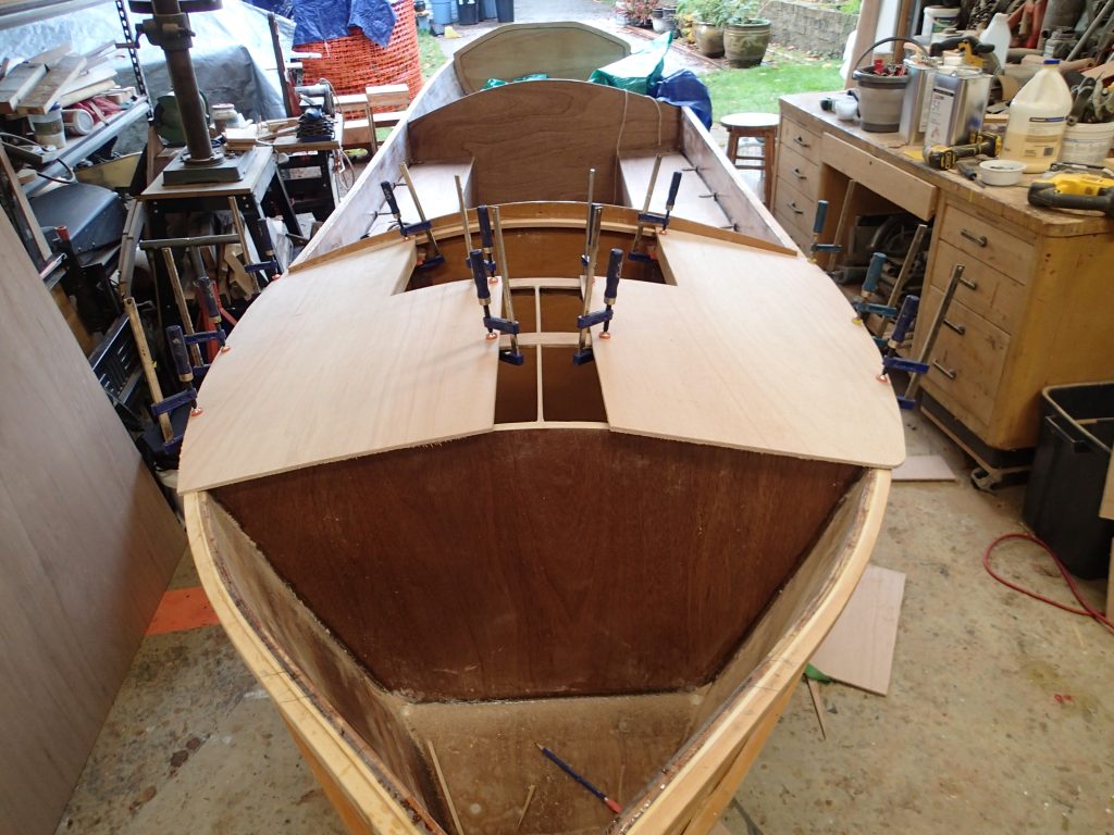
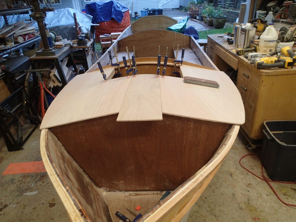
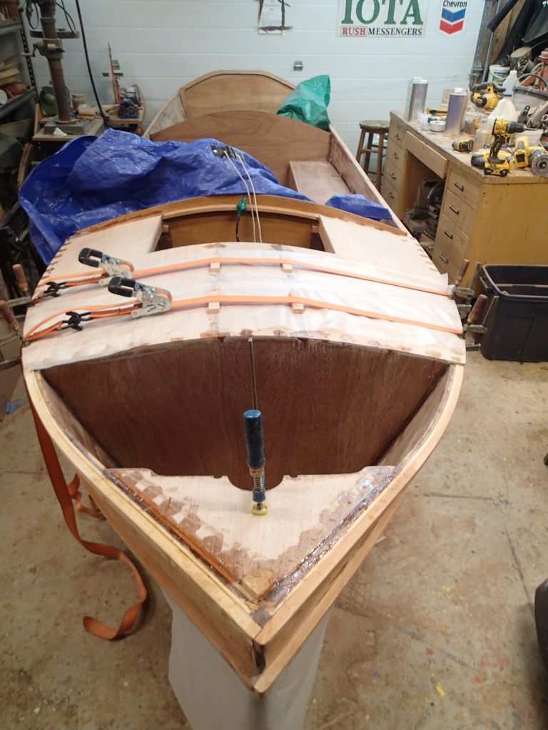
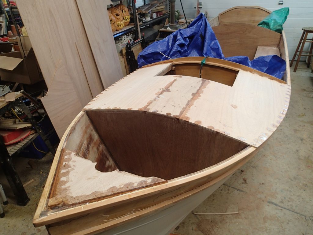
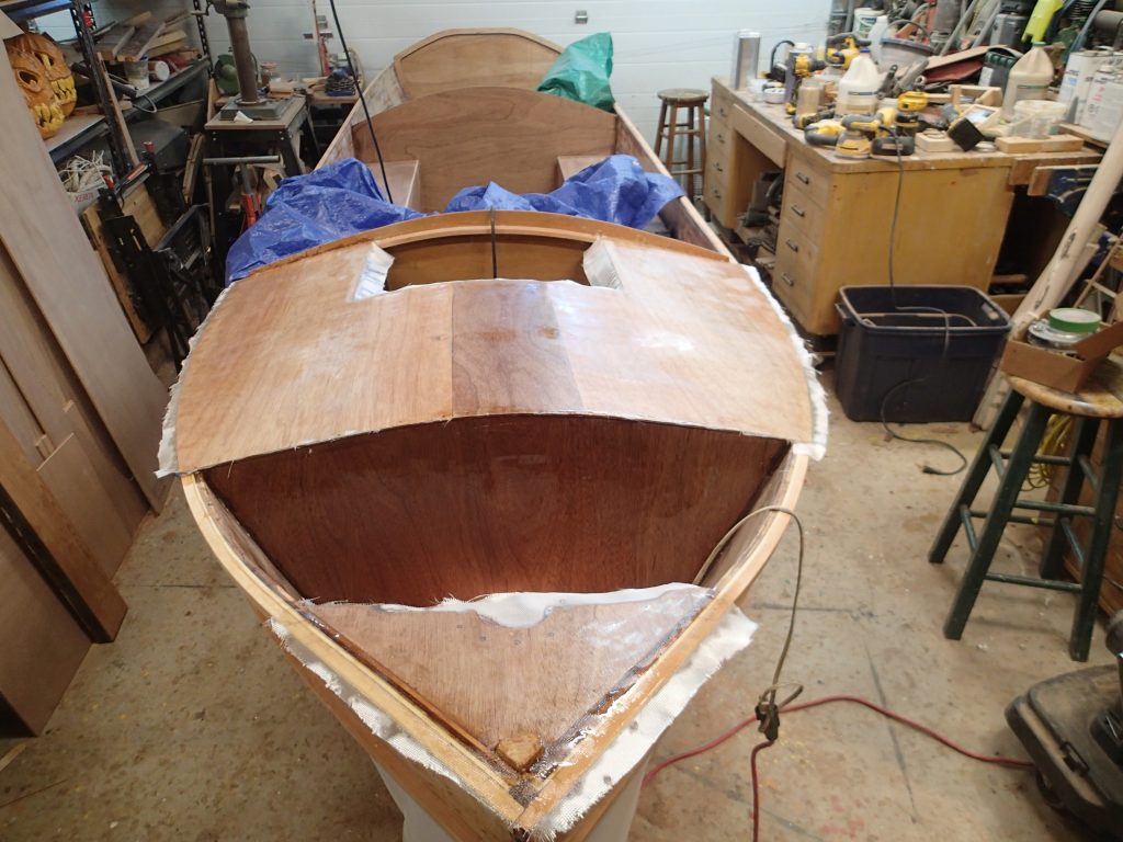
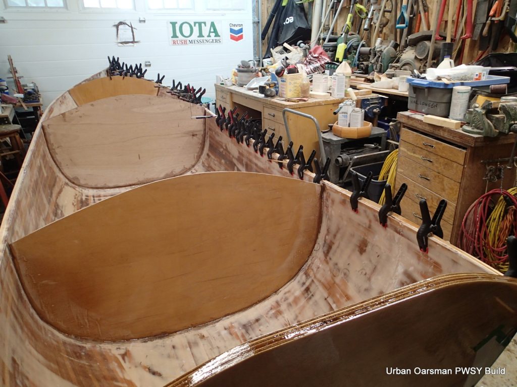
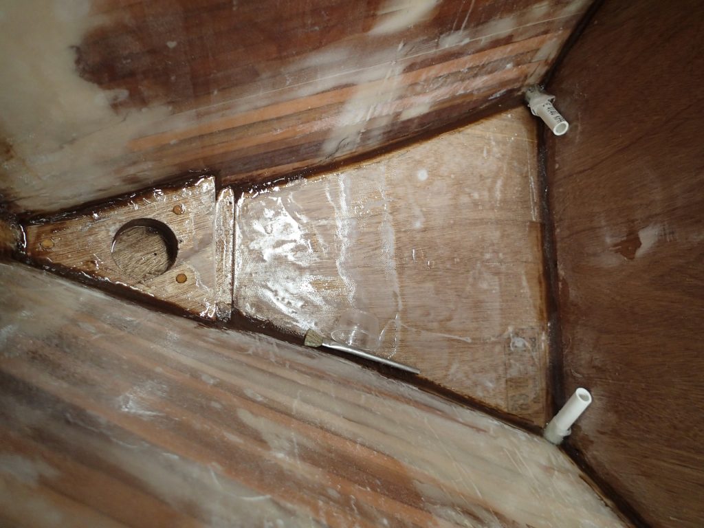
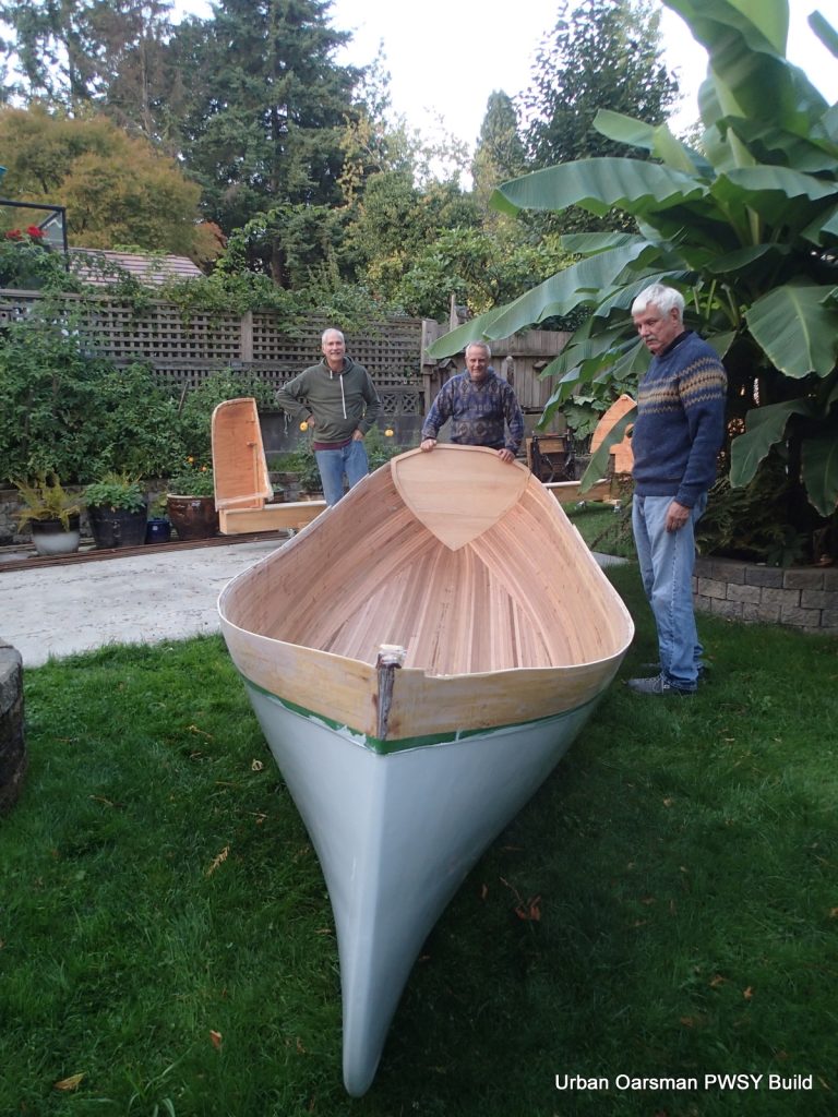
With the gunnels profiled, and the fore decks installed, a protective layer of epoxy and cloth is applied. The stems have also been trimmed to shape. When the seat goes in, I will have a bow and a stern!

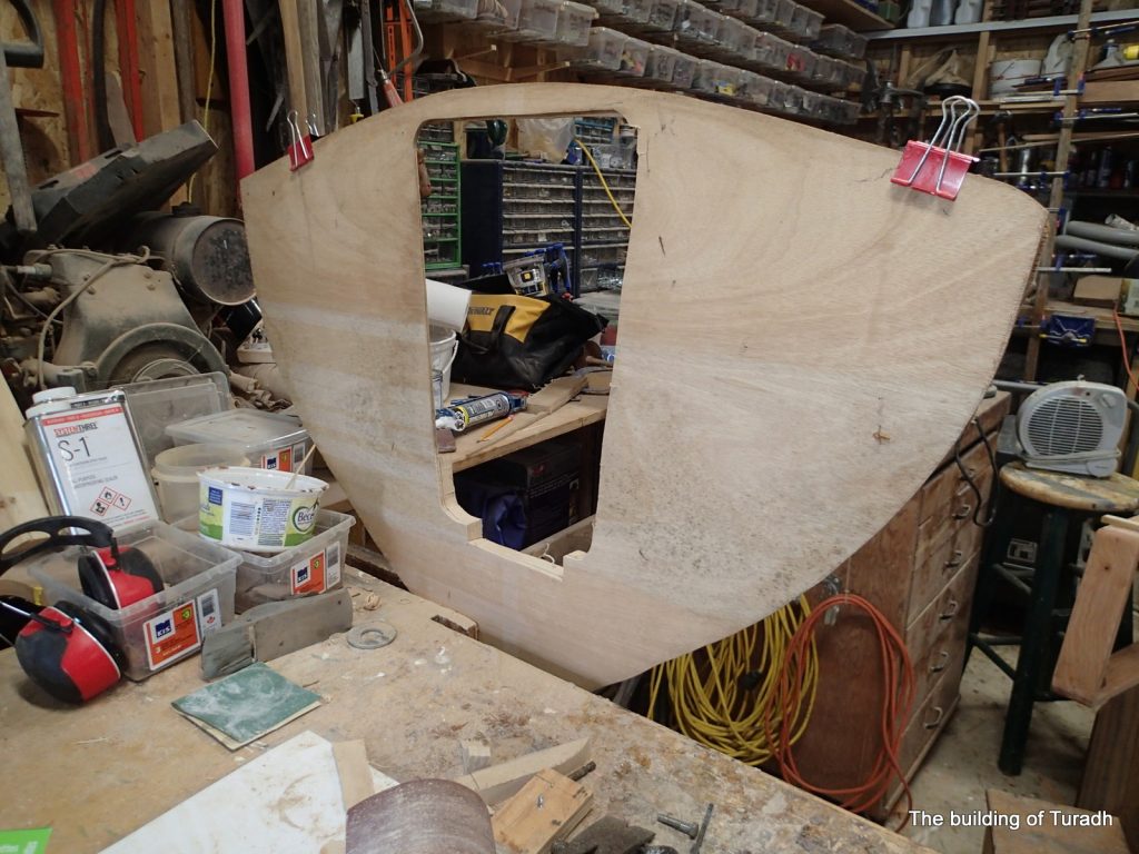
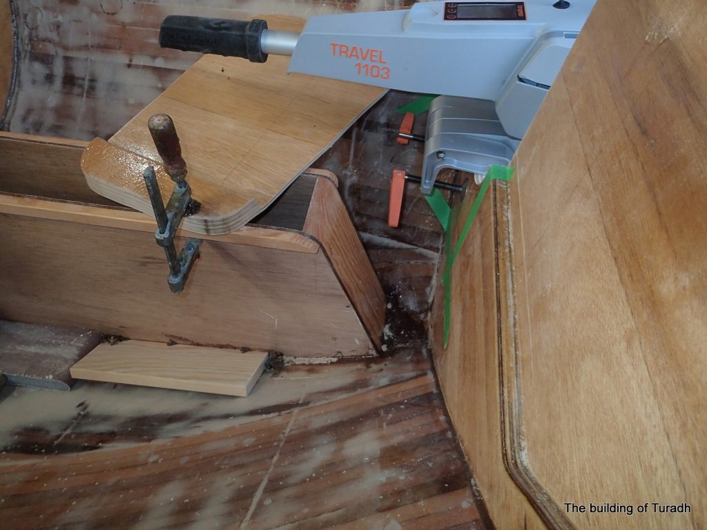
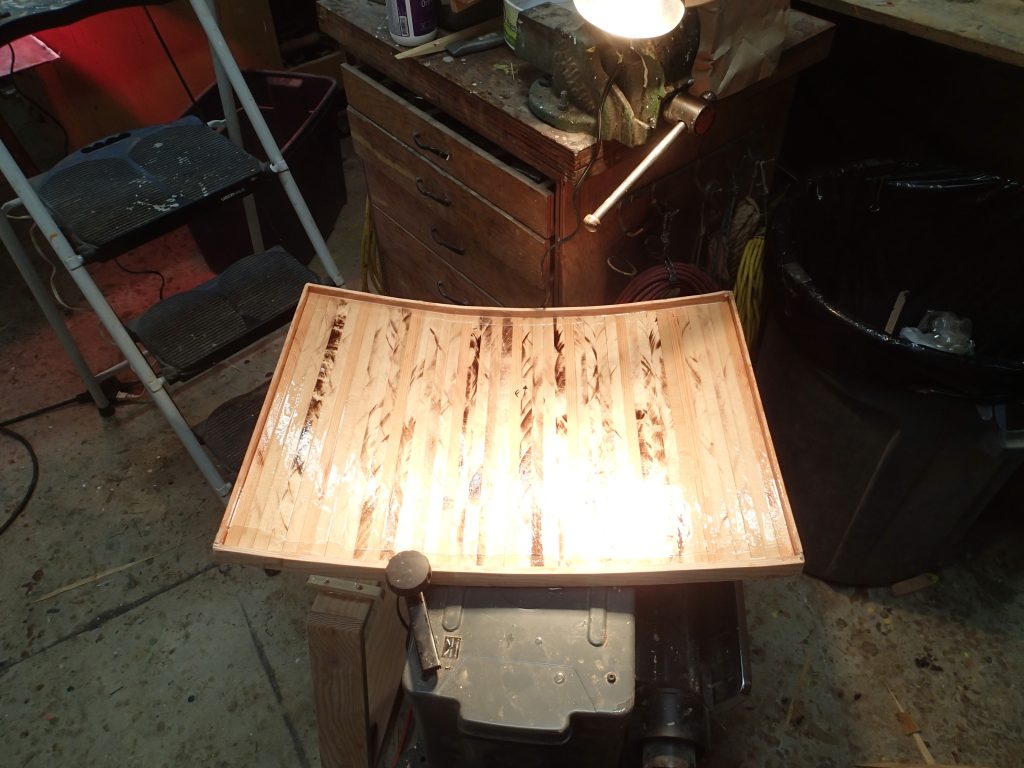
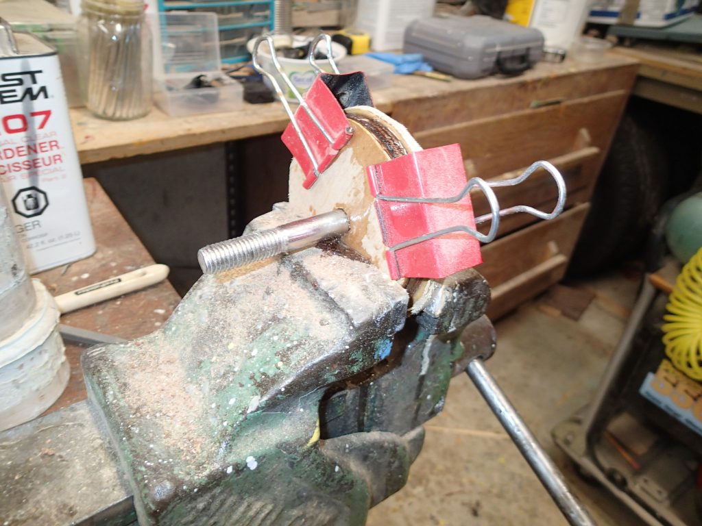
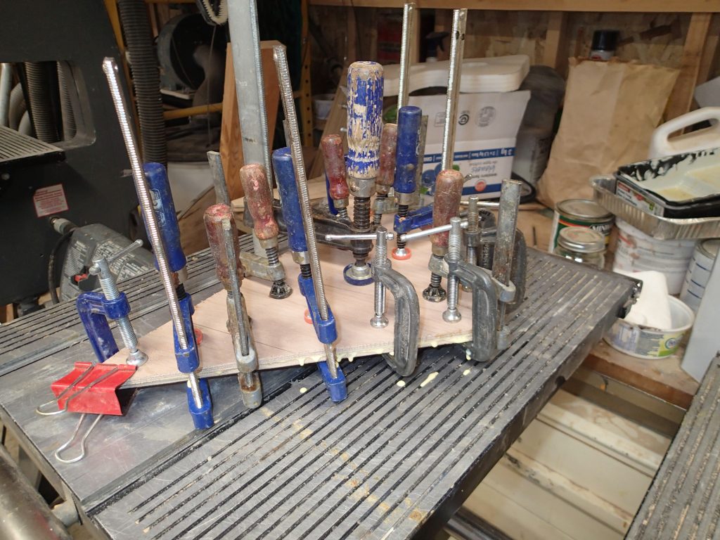
I am making the seat back from left over yellow cedar. I have cut two curved pieces and glued them together.
I used form #0 to get the shape for the seat back.
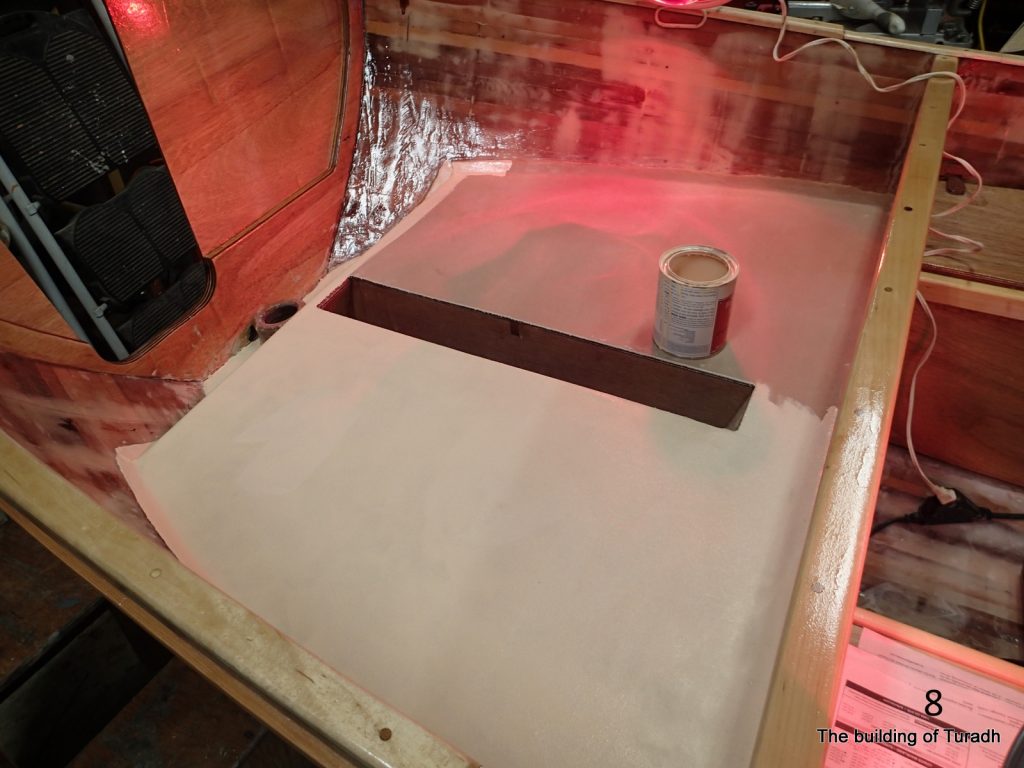
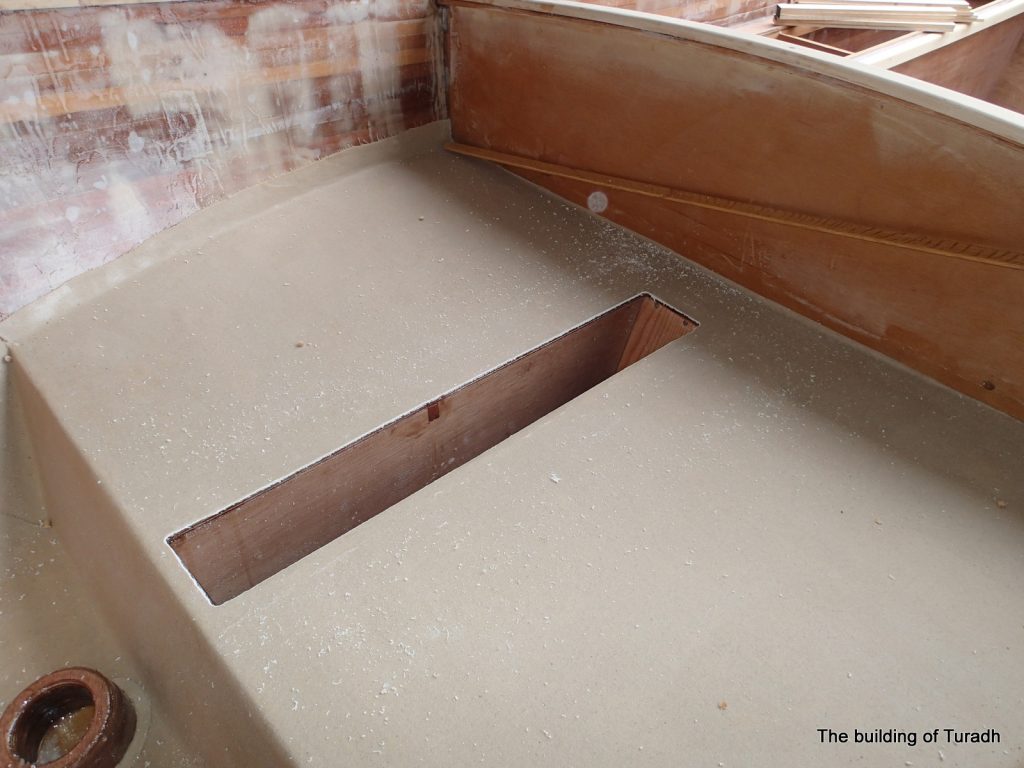
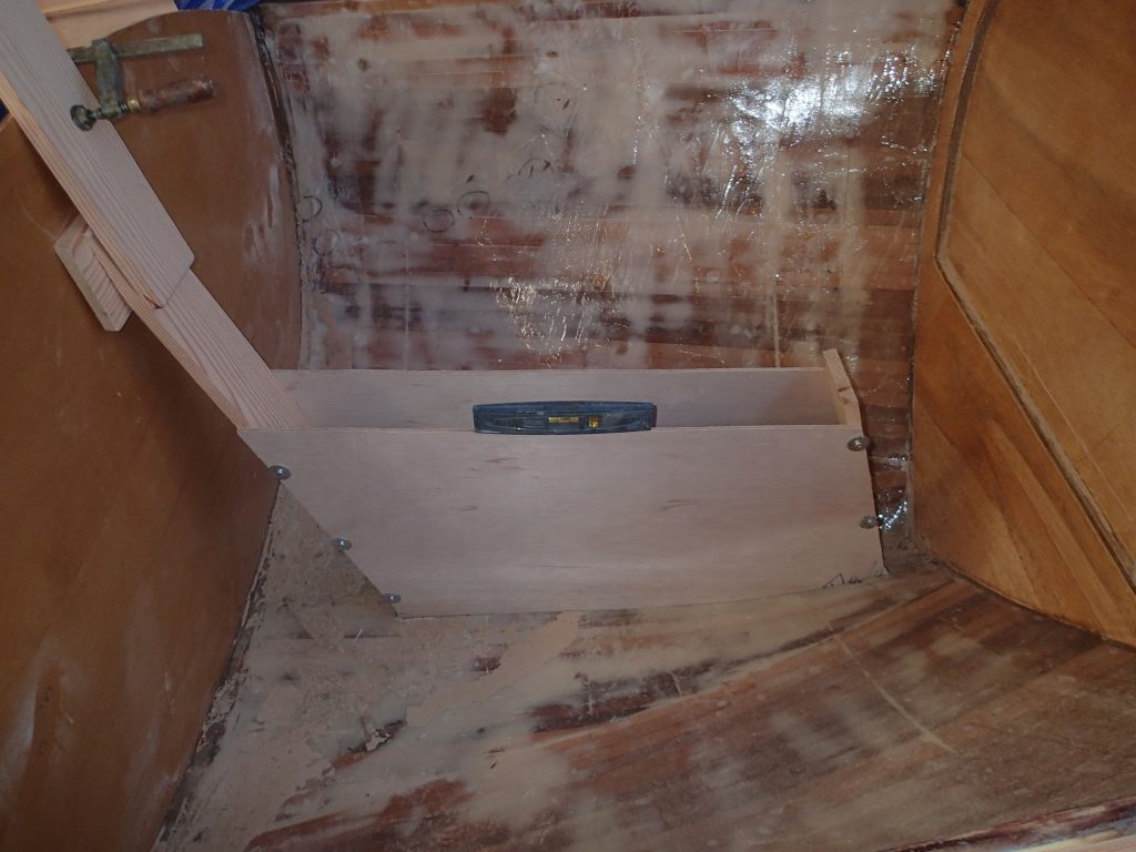
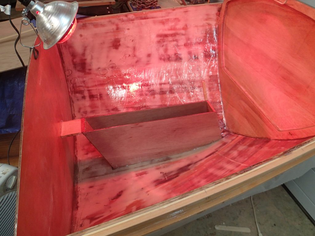
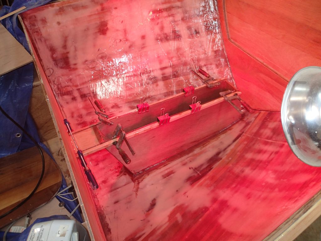
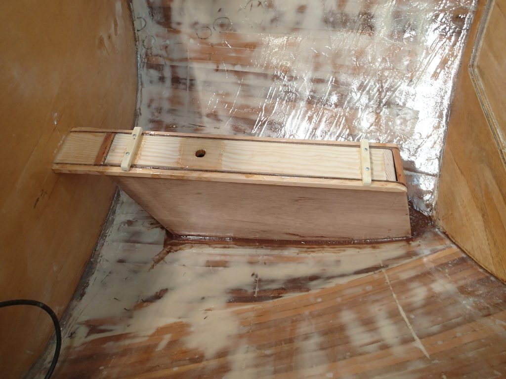
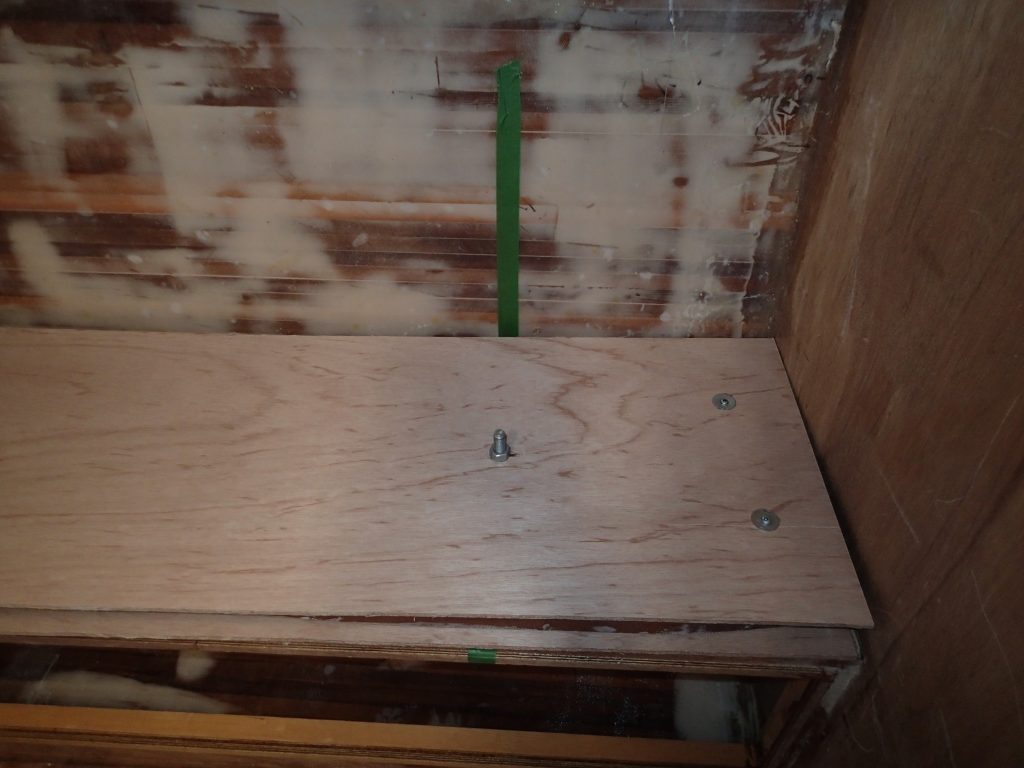
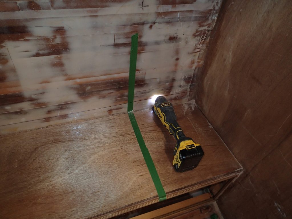
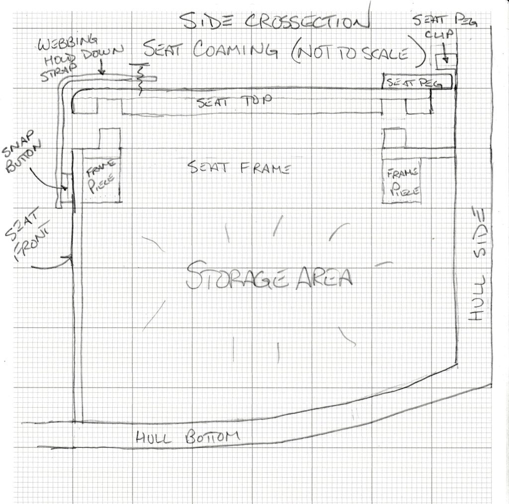
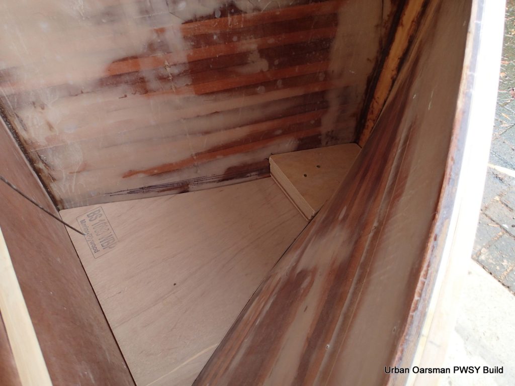
The seat base is from Paul’s canoe. He asked me to move the seats in the canoe to make it more comfortable for paddling. I had two cane seats and used them in Paul’s canoe. I am using his old seat here. It is screwed into two runners epoxied to the floor of the canoe. I have also put in four “D” rings to tie stuff to.
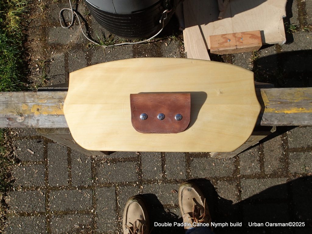
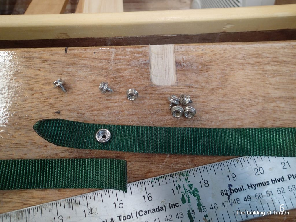
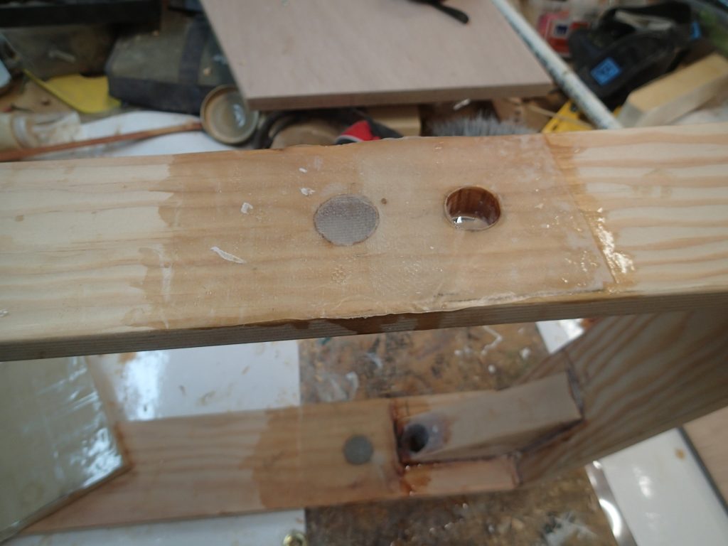
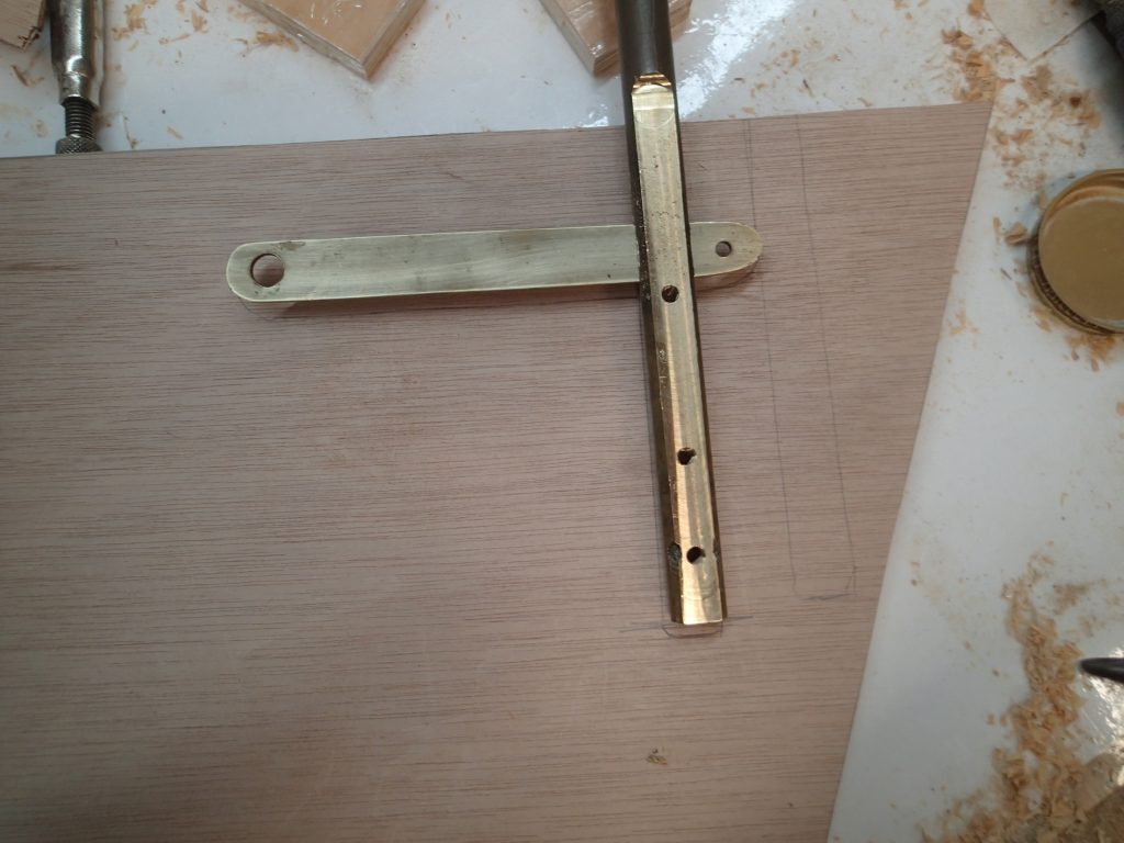
This piece of leather and snaps will hold the seat back to the thwart. It is somewhat adjustable.

The foredecks need some decoration. I scanned and printed onto onion skin a maple leaf from my garden. I then epoxied the picture onto the two decks, under the cloth.
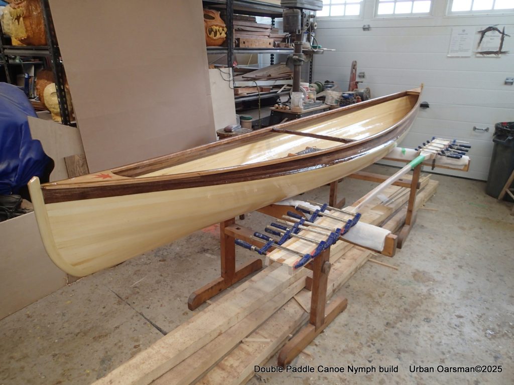
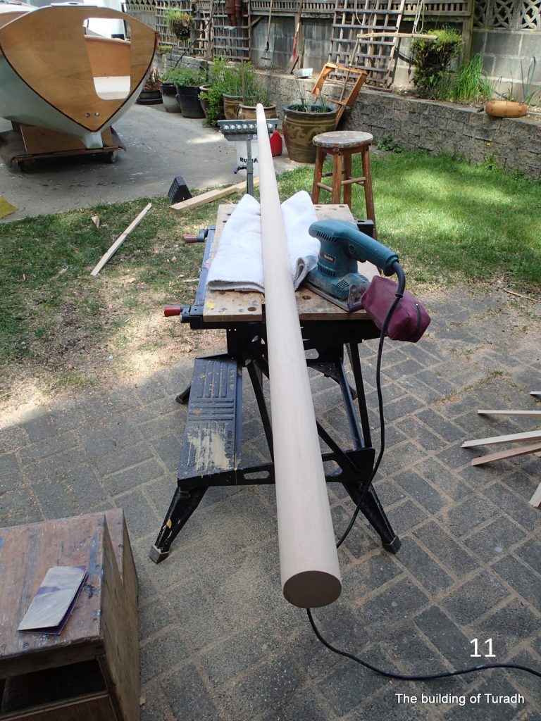
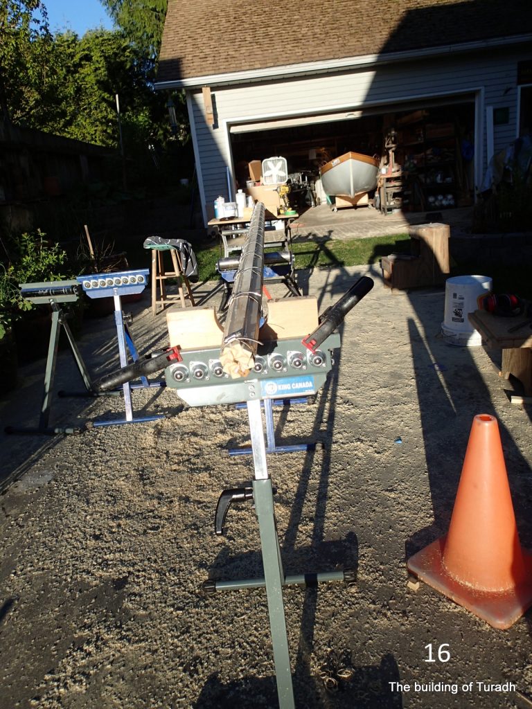
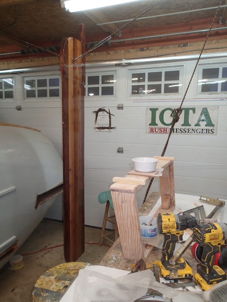
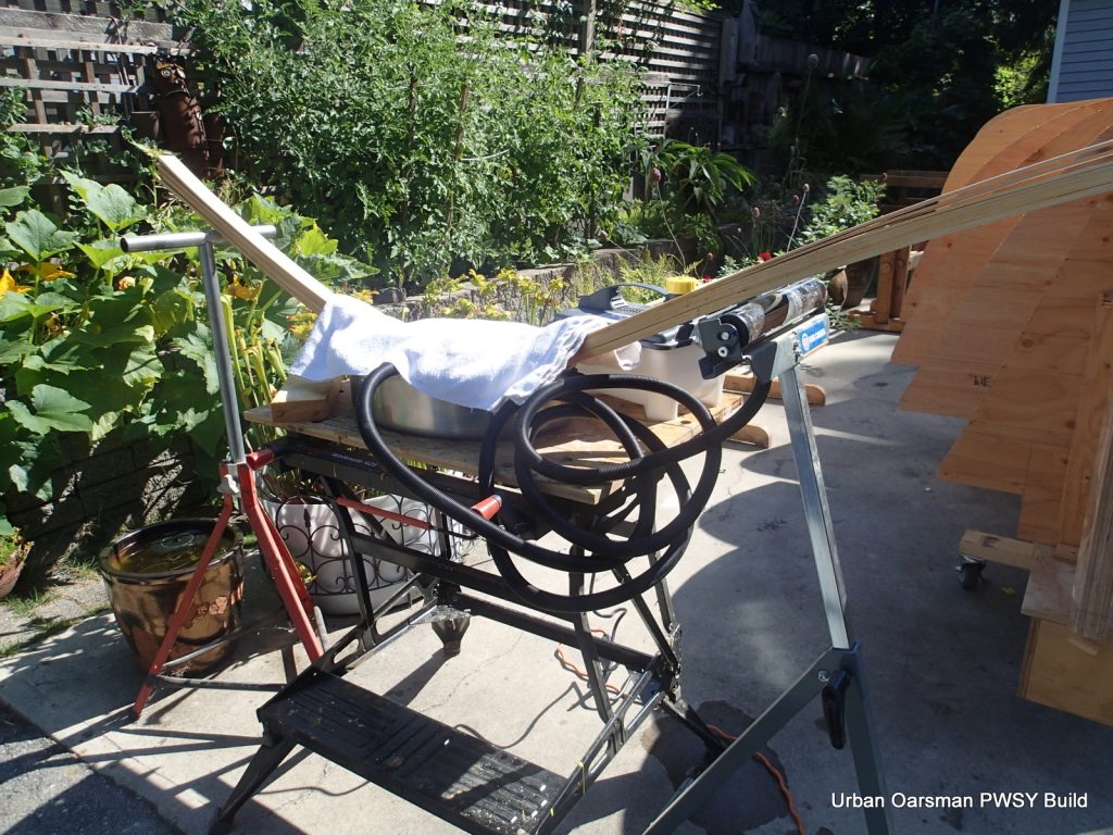
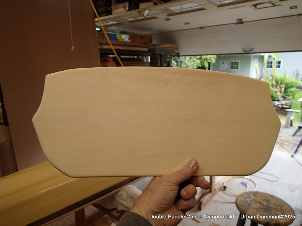
I am unsure as to how long my double paddle should be, so, while the varnish dries, between coats, I make a second longer double paddle to go with the double canoe.
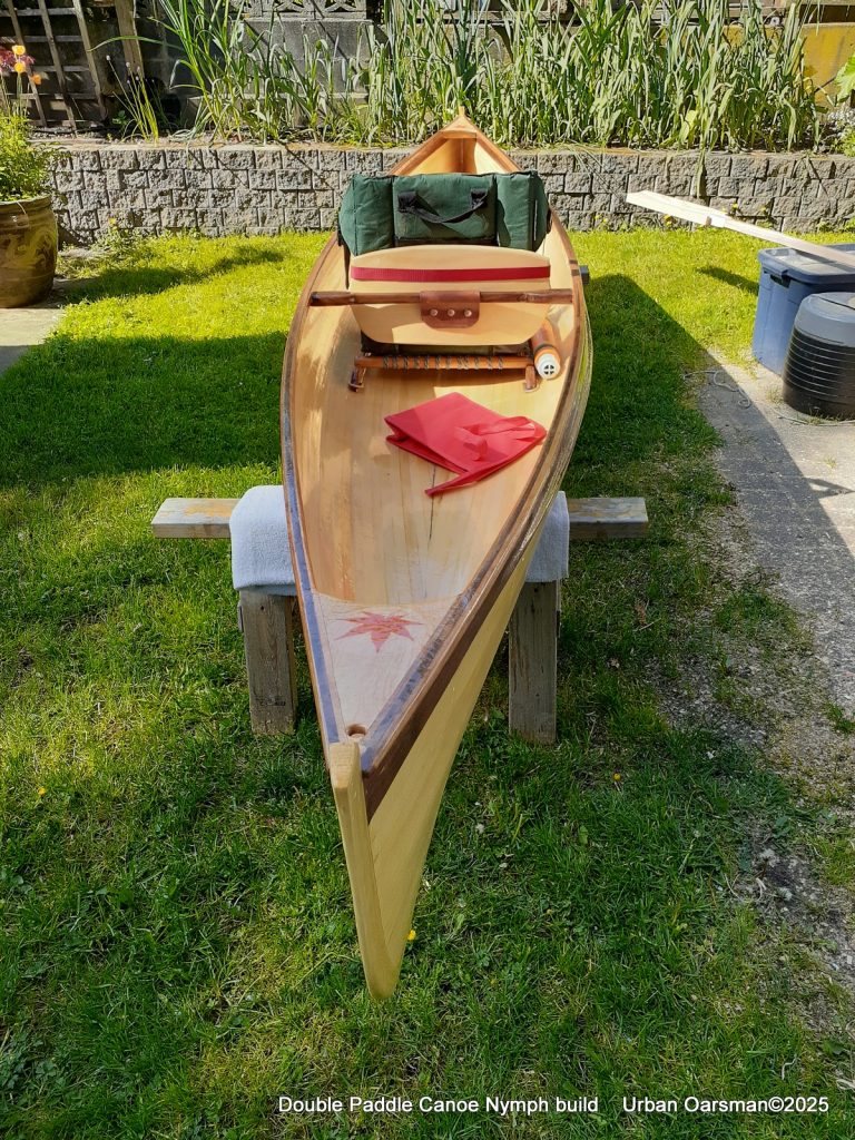
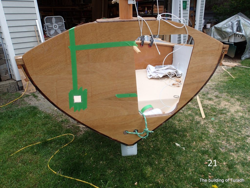
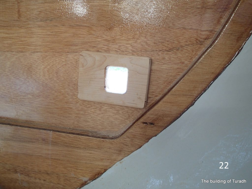
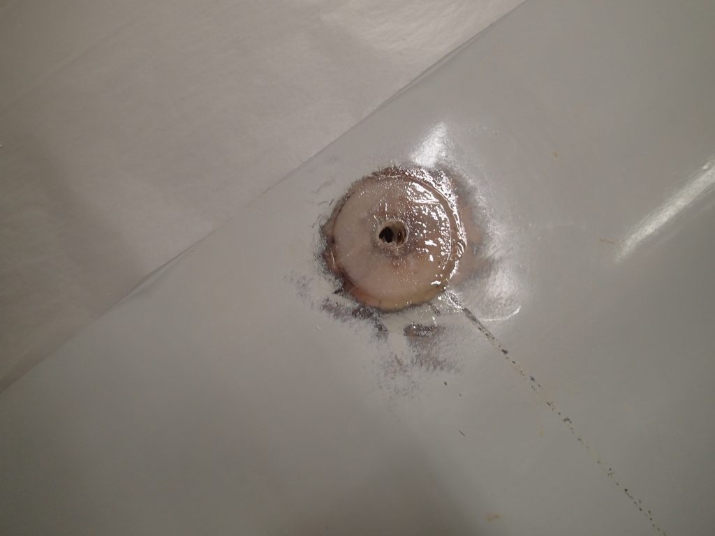
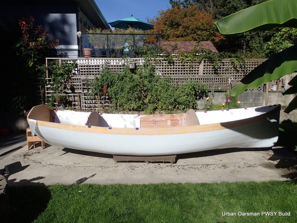
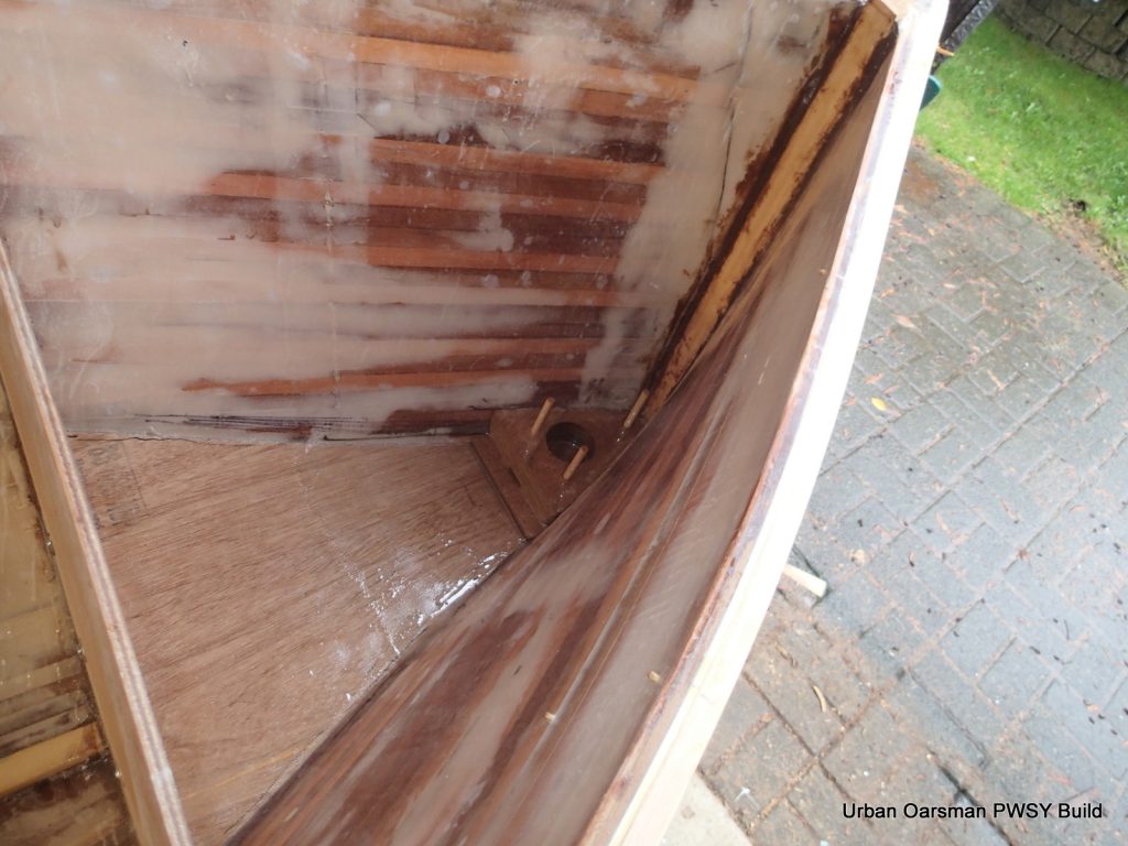
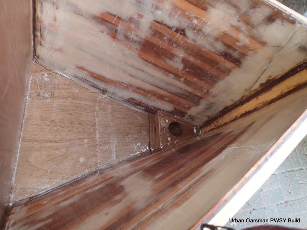
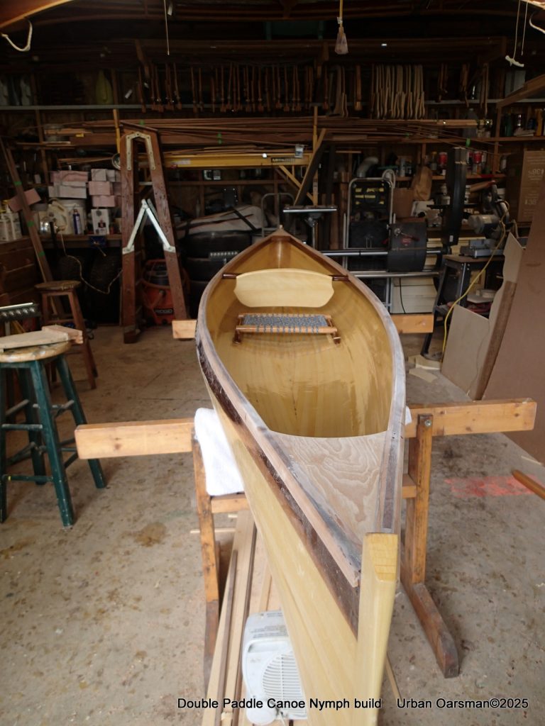
Fitting out the inside of the canoe. The red strap holds the stadium seat in place. You can see the pump to the Starboard of the seat. The holes in the foredecks allow any water to drain in case the canoe is stored upside down. I also use the holes to attach a bow and stern line.
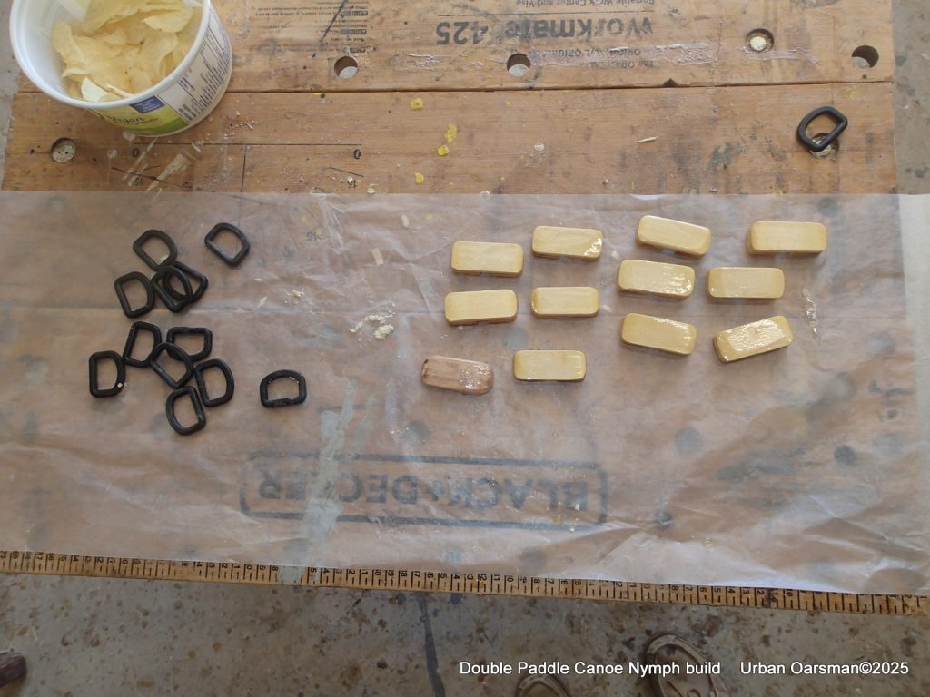
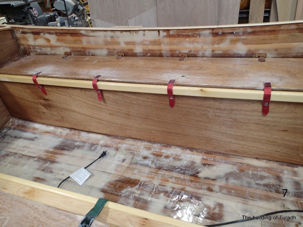
I do not think that you can have enough tie-downs, so I made up a dozen more for the canoe. As the “D” rings are plastic, they are not meant for a big load. I will thread shock cord through them to keep stuff in the canoe. It is also Potato chip snack time.
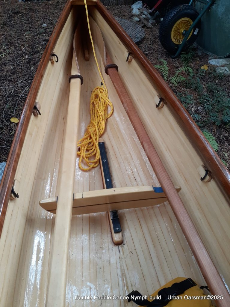
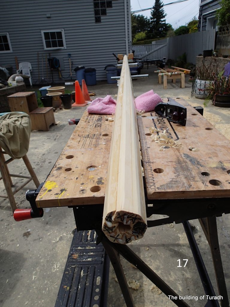
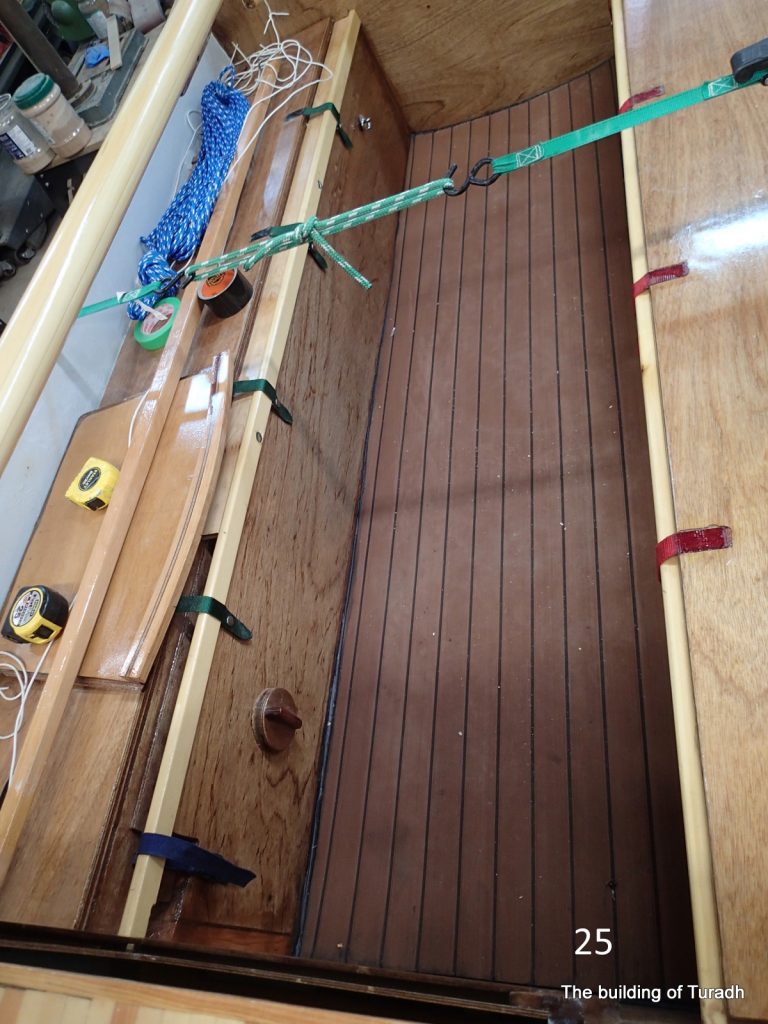
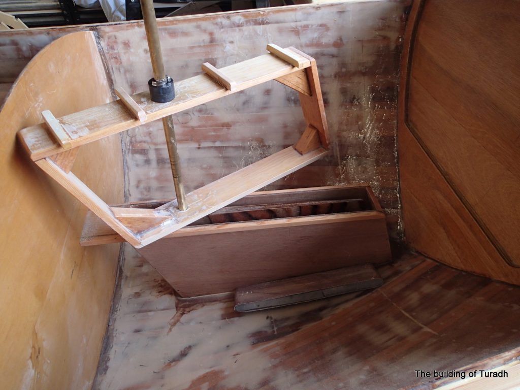
The foot rest is adjustable. The forward tie-downs are in the photo as well as the two double paddles that I made. The shaft for the double paddle on the right was make from a left-over stair-case railing. All of the blades have been epoxied for strength. Bees wax coats the shafts. Protects the wood like varanish, but, is much easier on the hands.
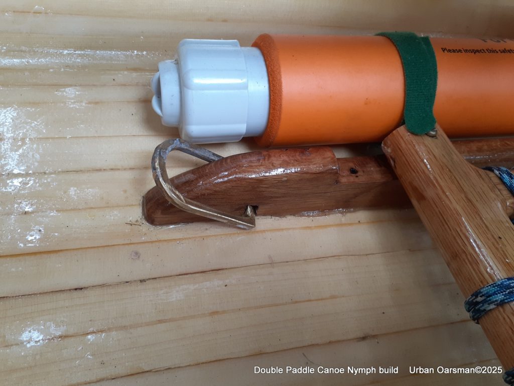
Pump held in place with Velcro. Close-up of one of the “D” rings. The seat rail has a notch to allow for some adjustment. The seat is in the after position.
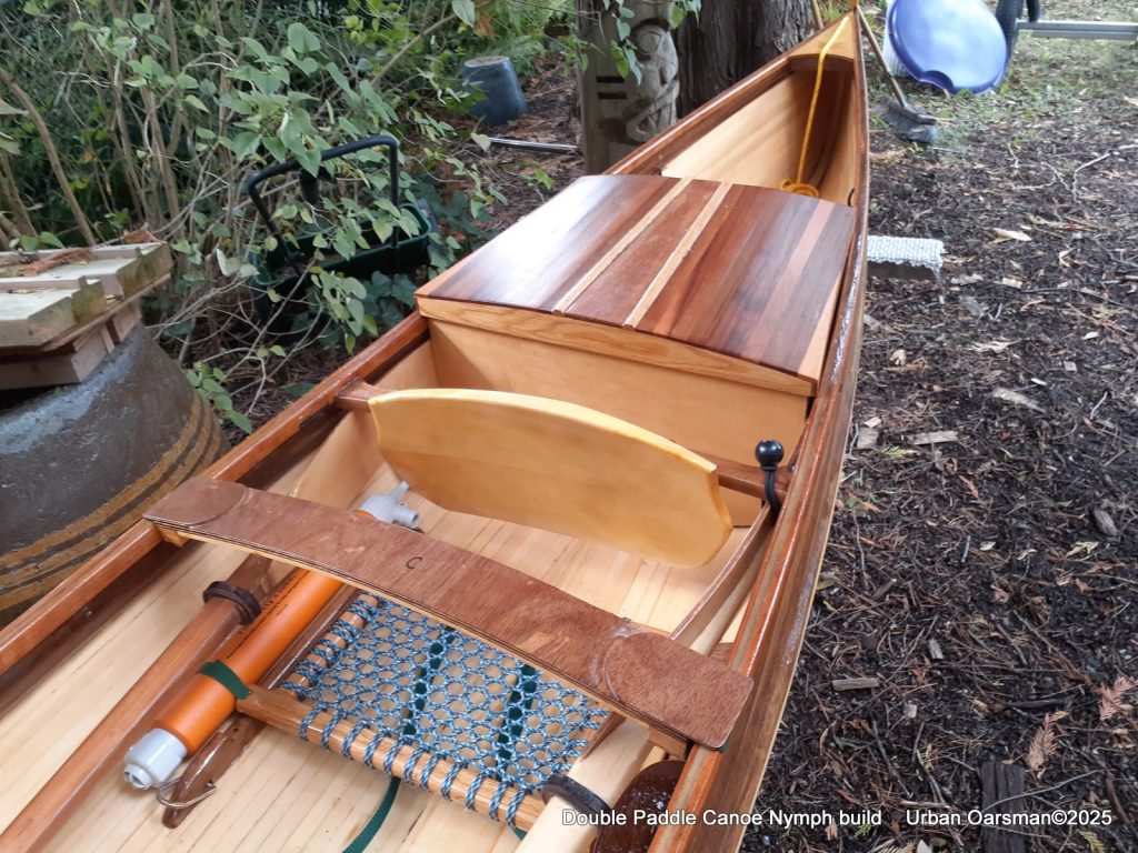
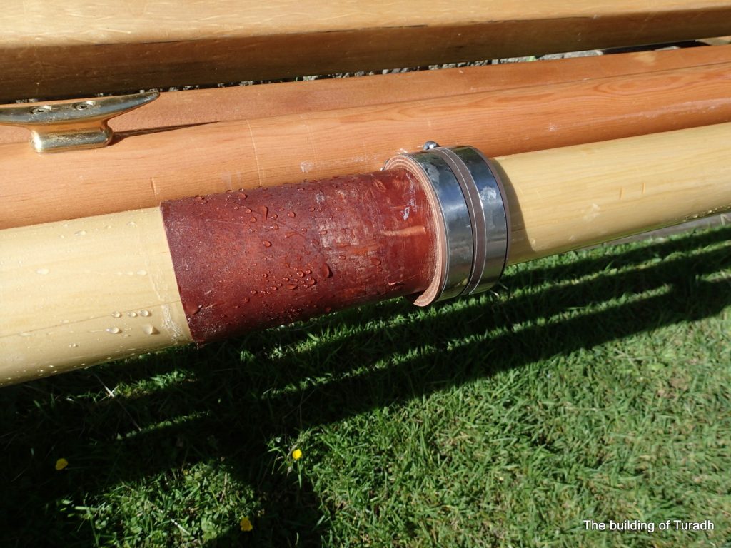
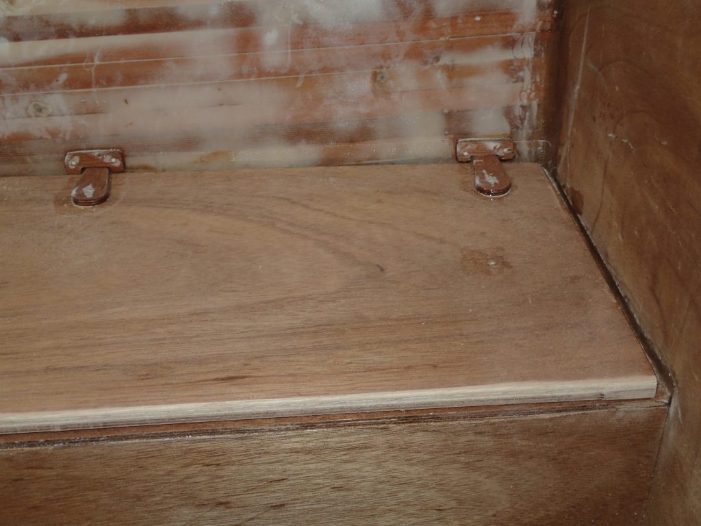
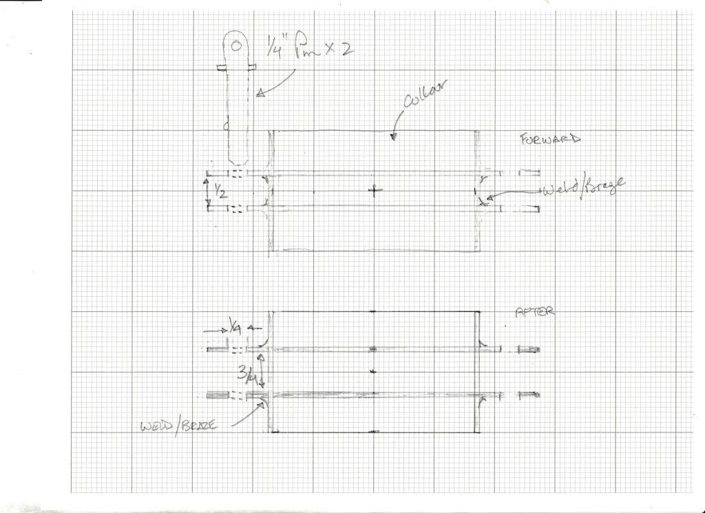
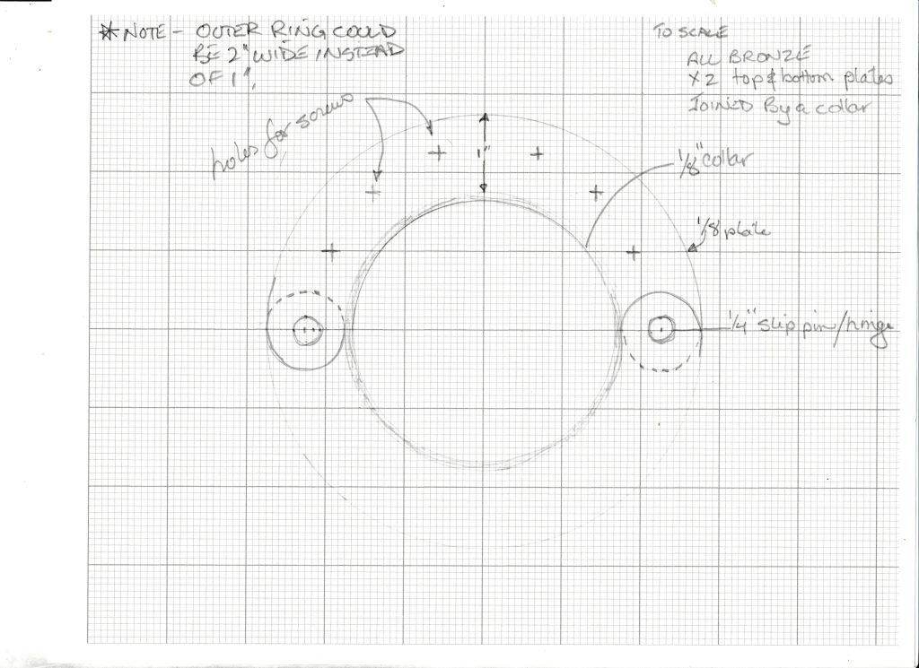
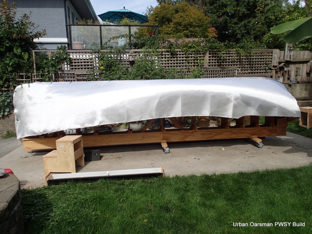
Seat, showing my “Lunch” box and the drip rings for the double paddles. The box is held in place by a green strap that snaps onto two of the cover snaps. The drip rings are made from strips of leather, wound around and glued to the shafts. The removable cross piece keeps the cover up and helps the rain run off of the cover. For transport, the double paddles fit between the lunch box and the hull. A bungee makes everything secure.
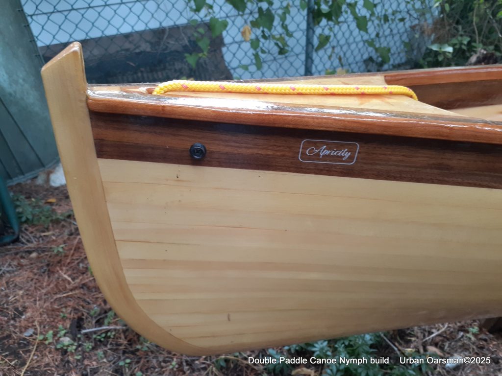
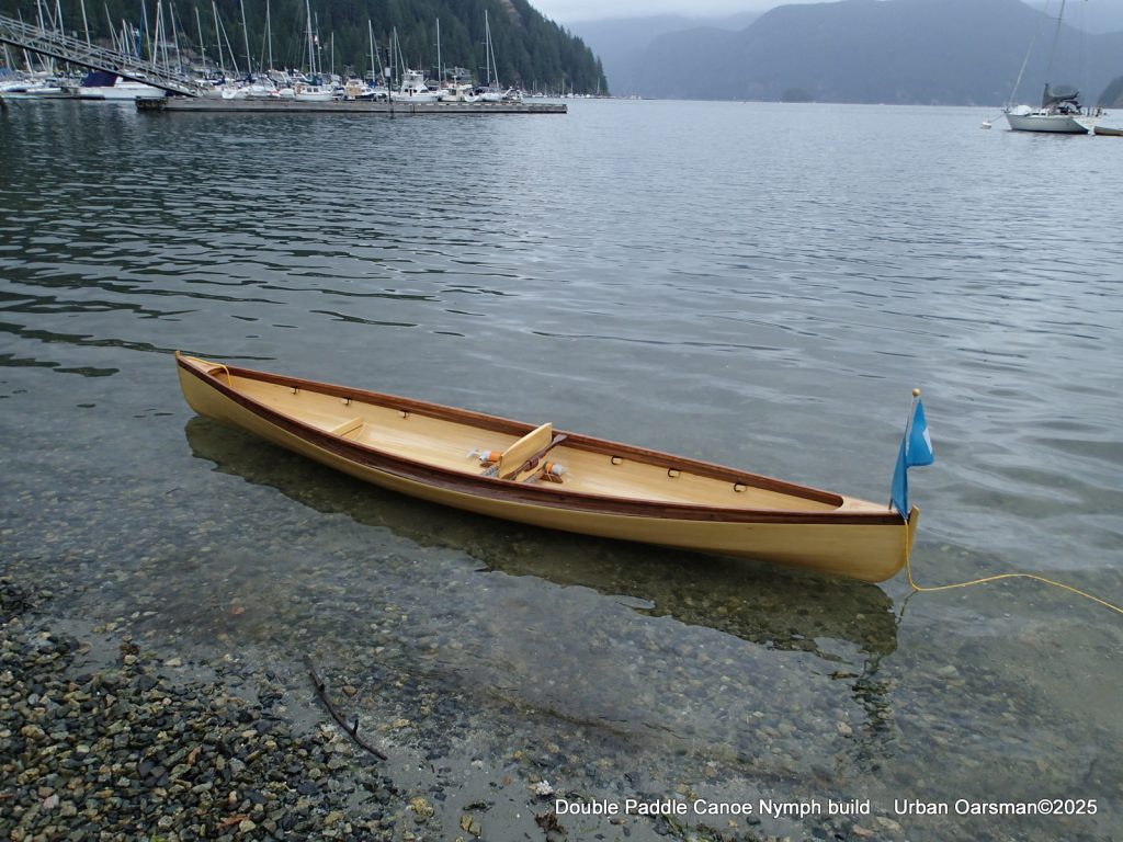
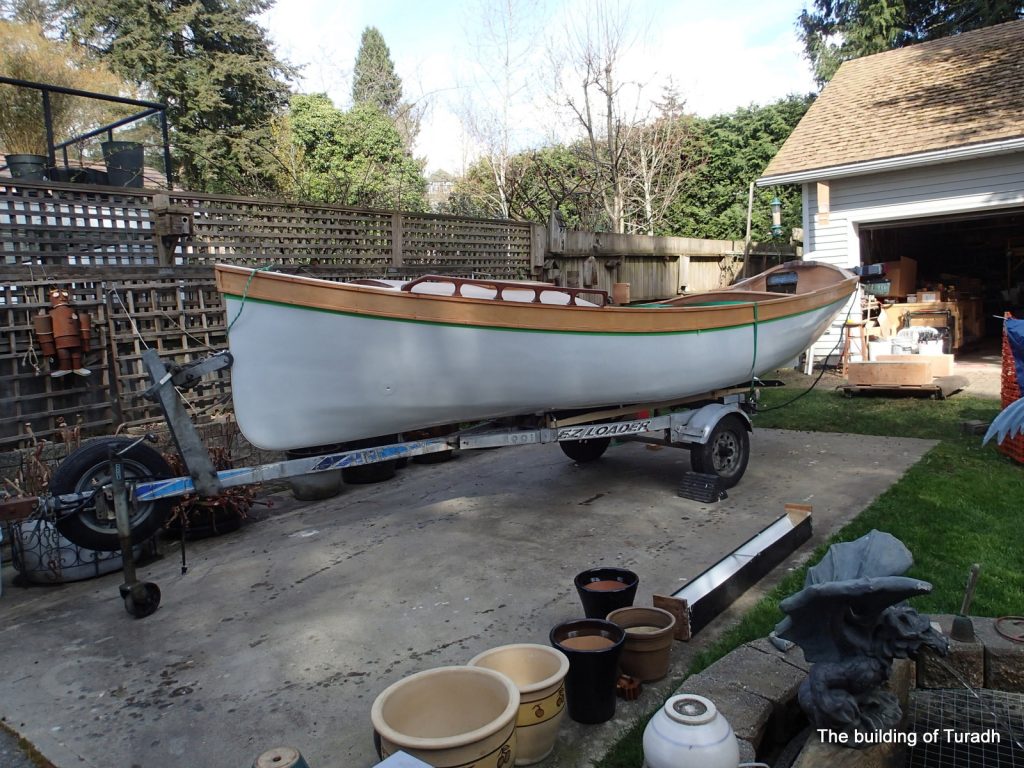
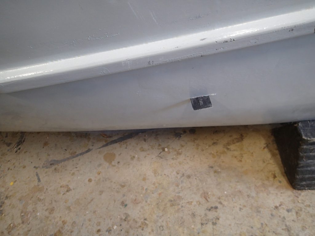
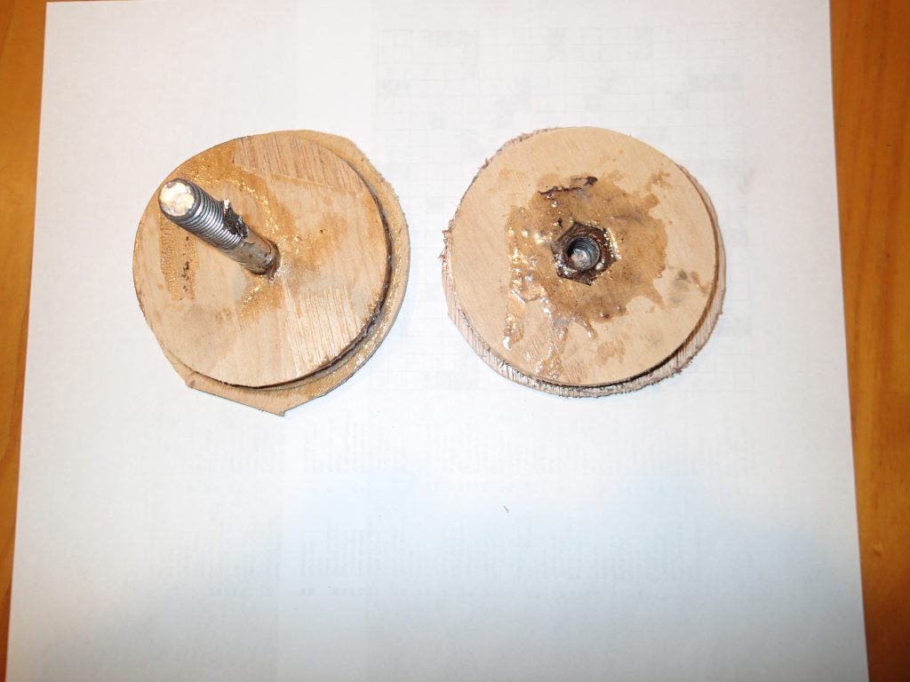
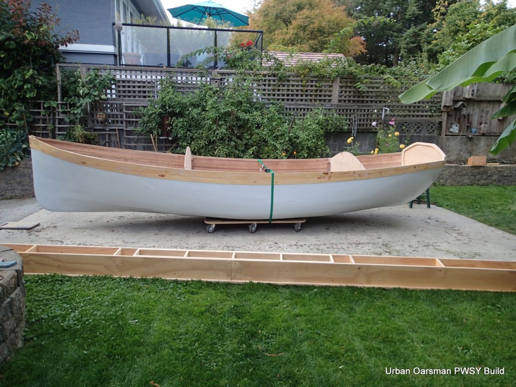
My double paddle canoe is named “Apricity” which is a word for the warmth of the sun in winter. You can see one of the snap button bases for her cover. She ended up being about 32lbs. I credit her extra weight to using ¼” strips instead of ⅛”strips. I do not have and could not find ⅛” bead and cove router bits. Nick just butts the two strips together. I was not happy with that construction.
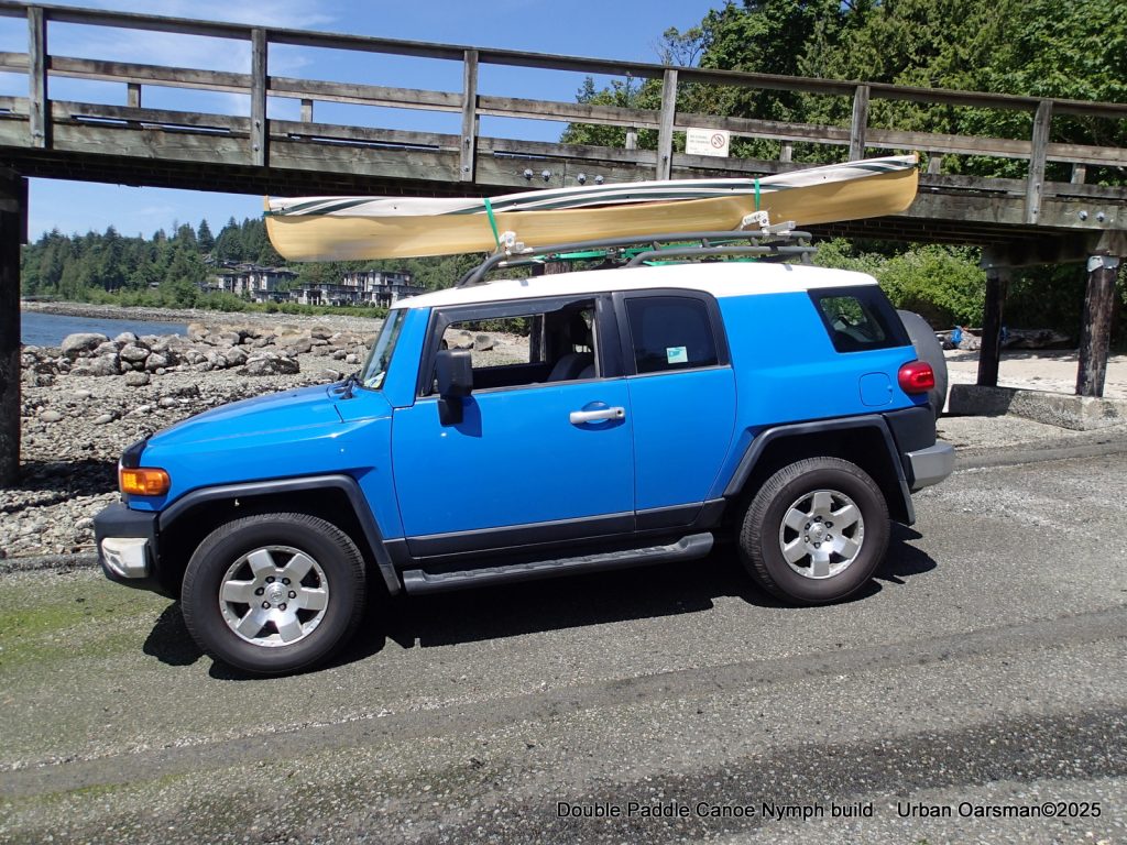
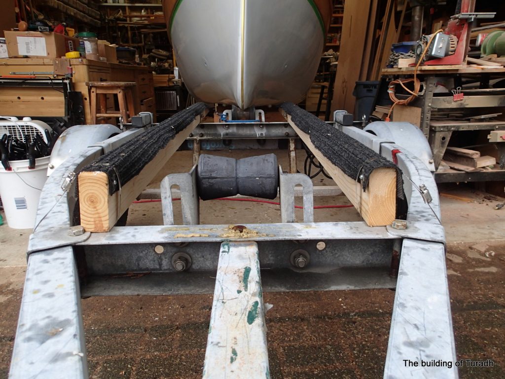
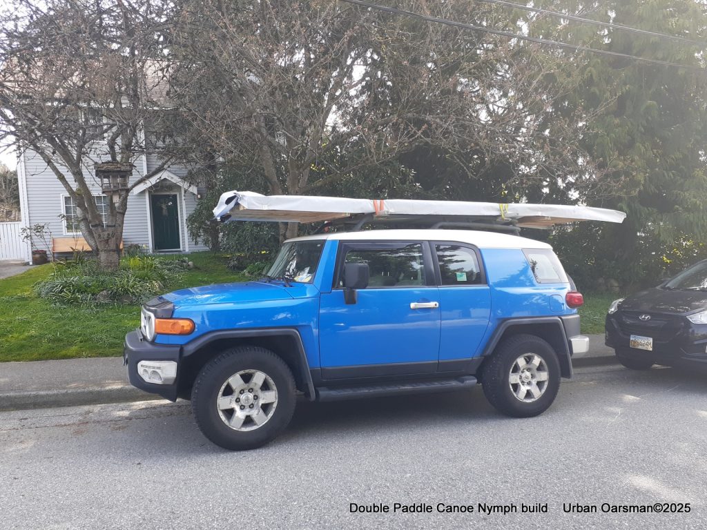
Apricity is easy to get up onto the roof rack. Here she has her cover on. By using the custom-fit saddles, I do not need a bow and stern line to tie to the FJ.
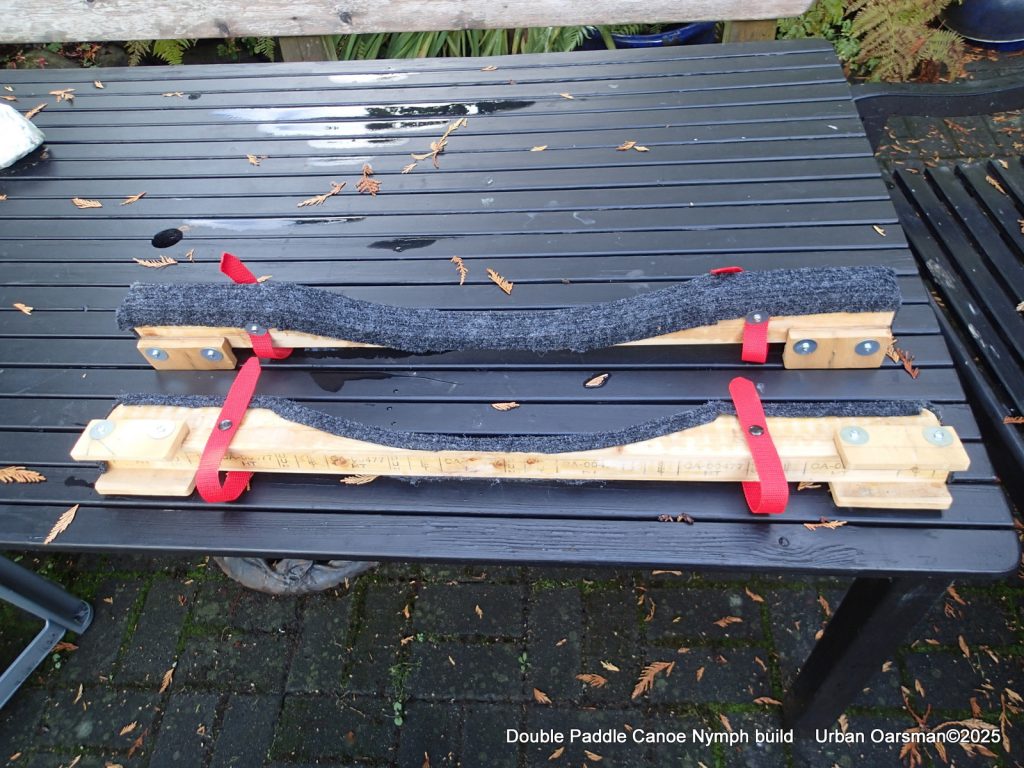
I made two saddles for her. The saddles conform to her bottom shape. I use one ratchet strap (green), it does not have hooks, it is just a long strap to hold her on. The red straps on the saddles are used to keep the saddles on the rack cross-pieces while loading or unloading.
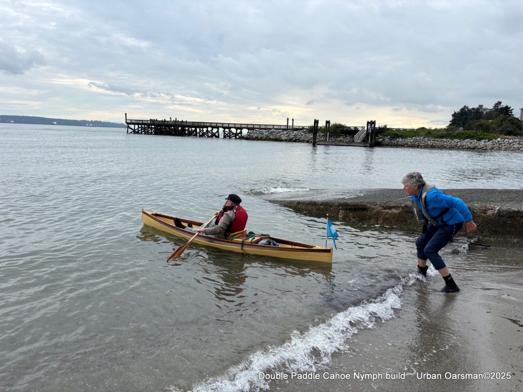
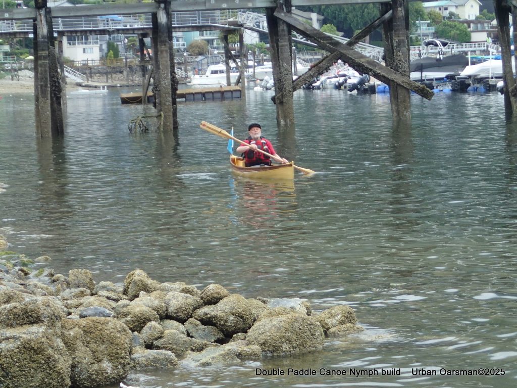
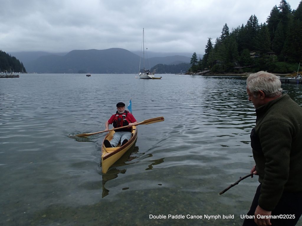
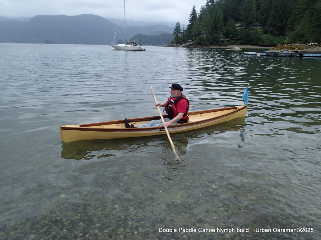
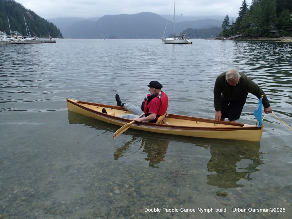
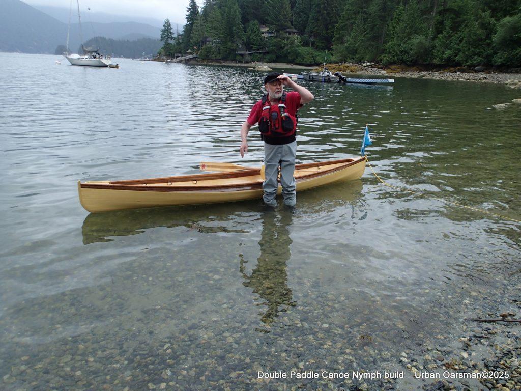
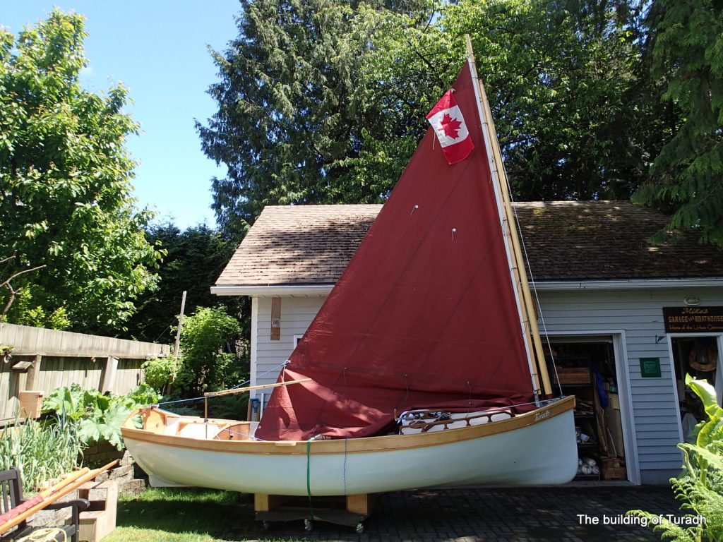
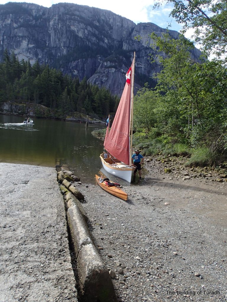
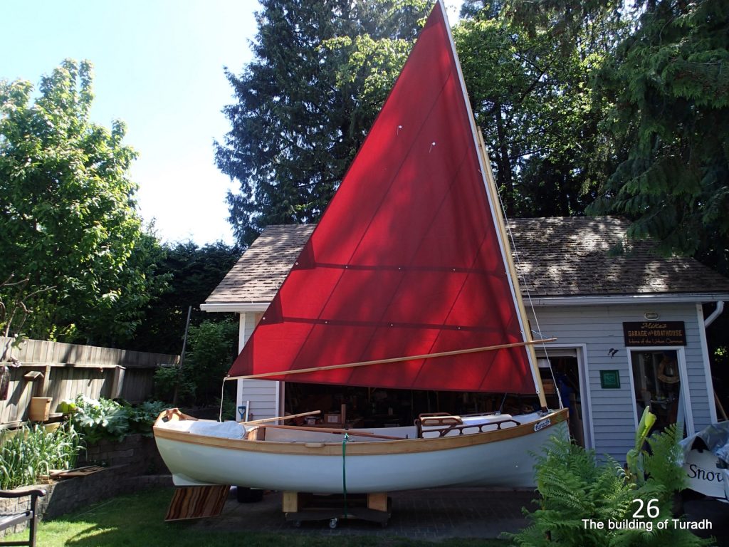
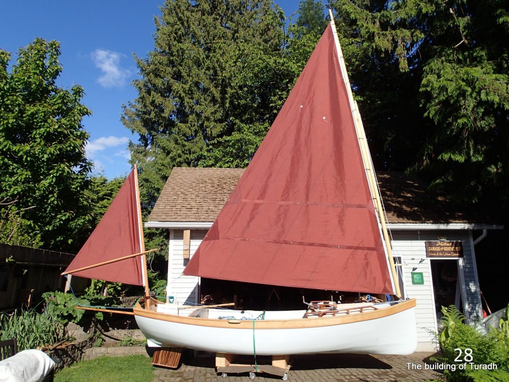
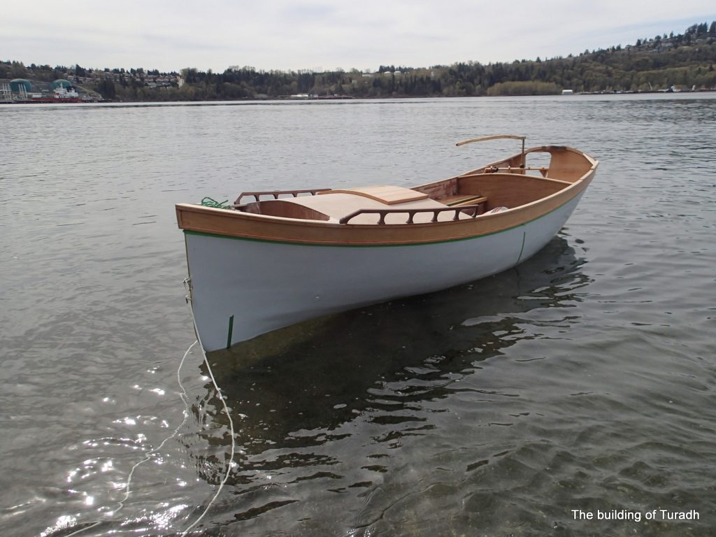
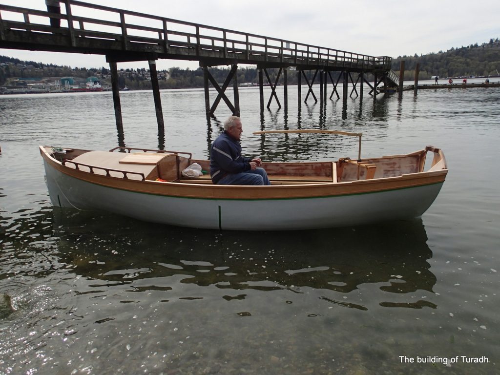
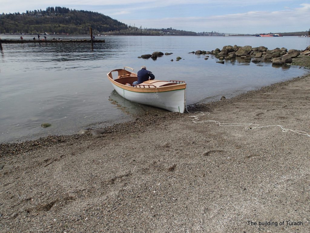
The official launch at the Hollyburn Sailing Club in West Vancouver B.C.
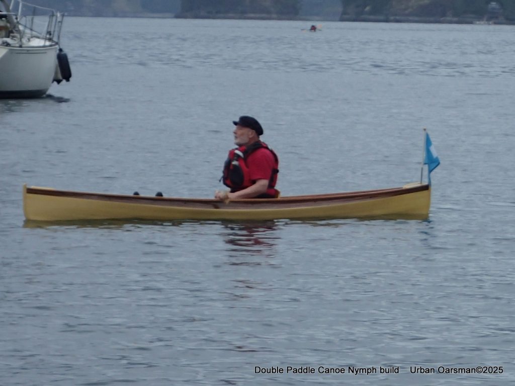
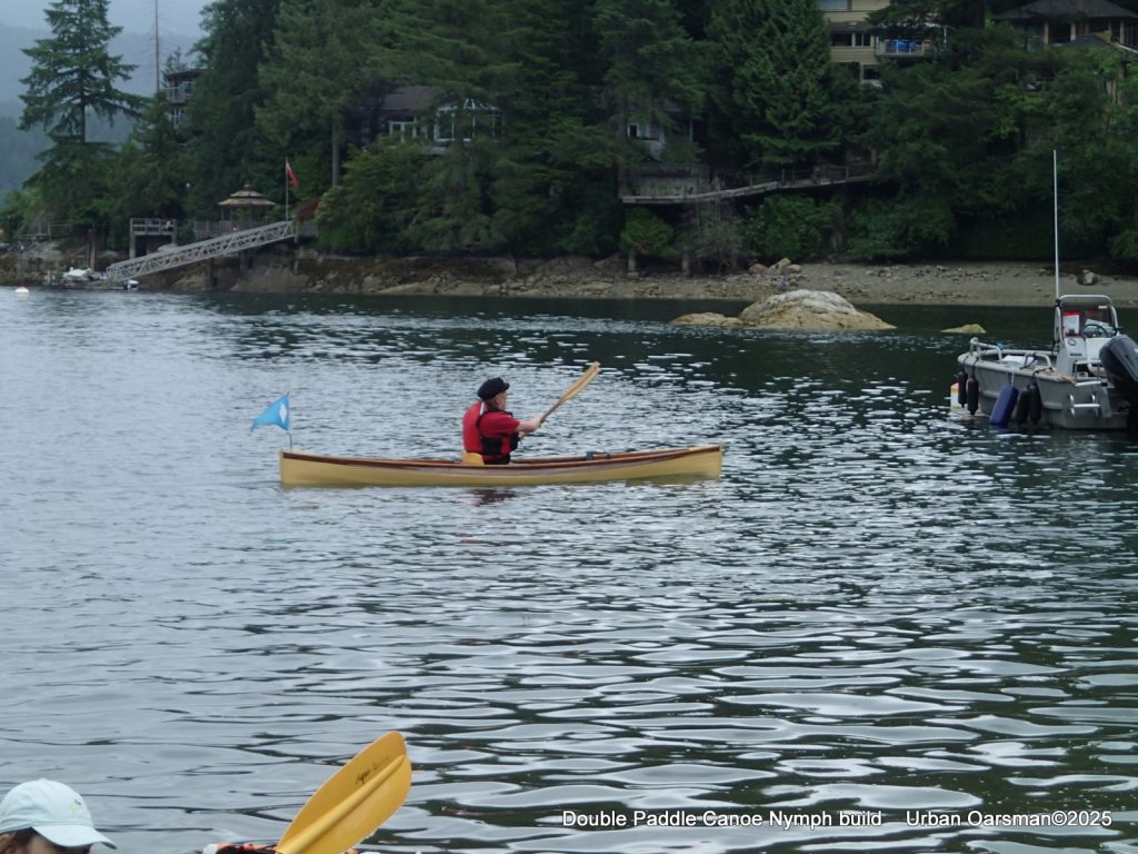
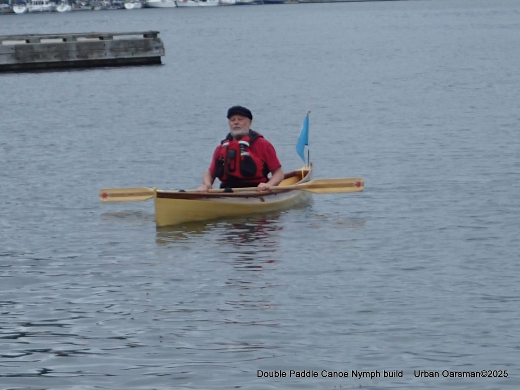
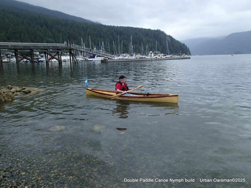
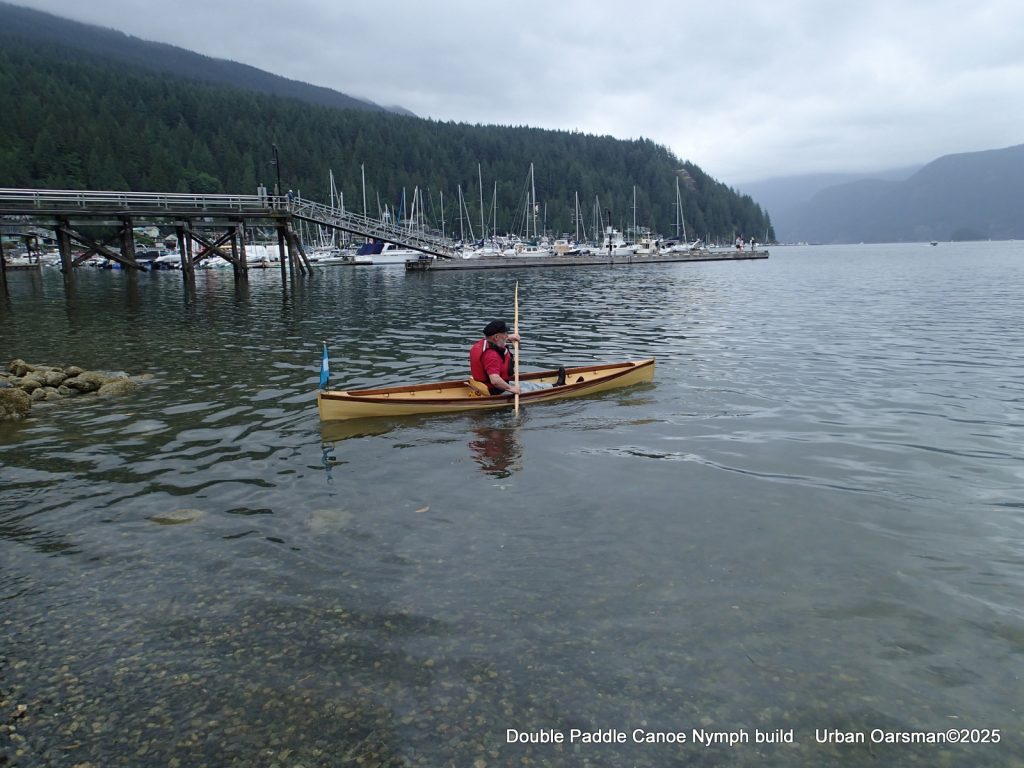
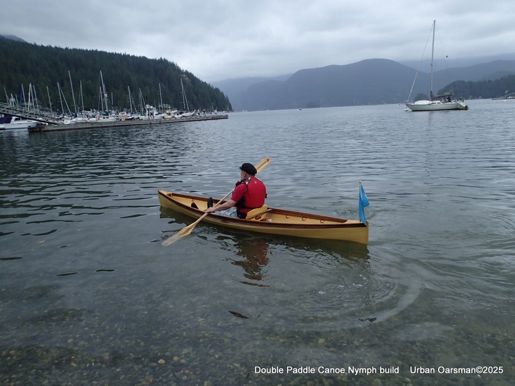
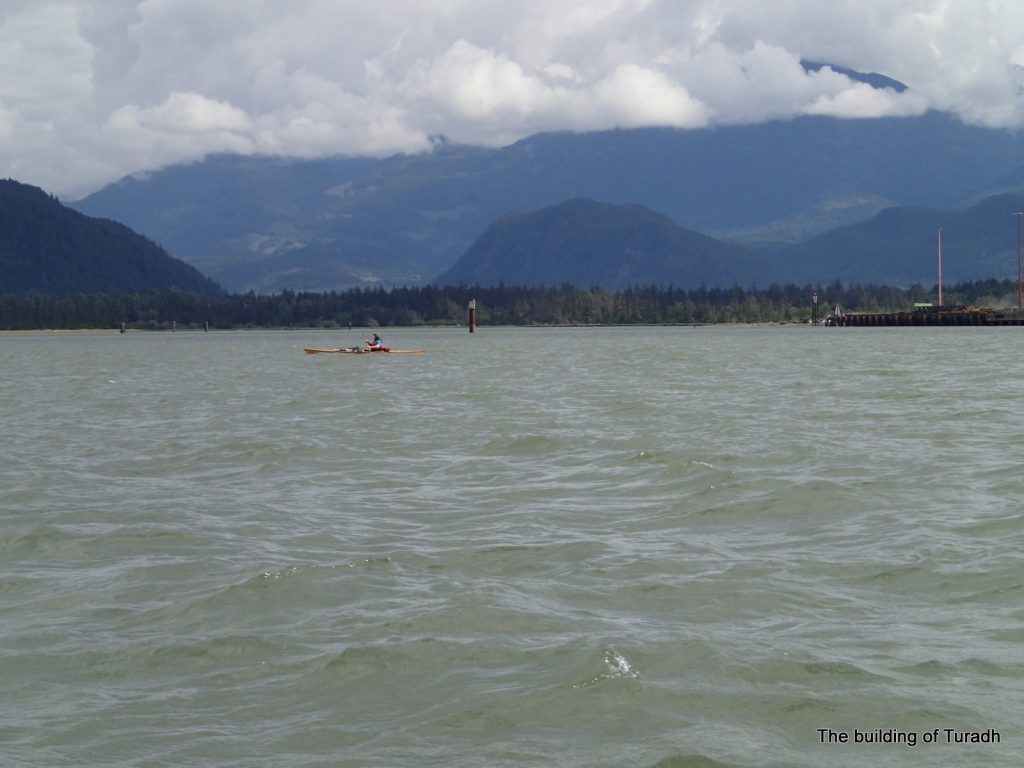
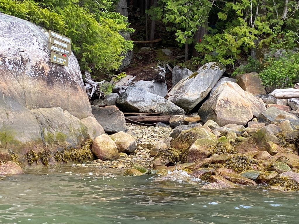
The following are a few photos from the “Builder’s Trials”.