
Centreboard Case, Rudder, Rudder Frame, Rudder Case and bottom plate.
It is still very cold here on the North Shore. It went down to -13°C (8.6°F) this week and it is very hard to work in such cold.
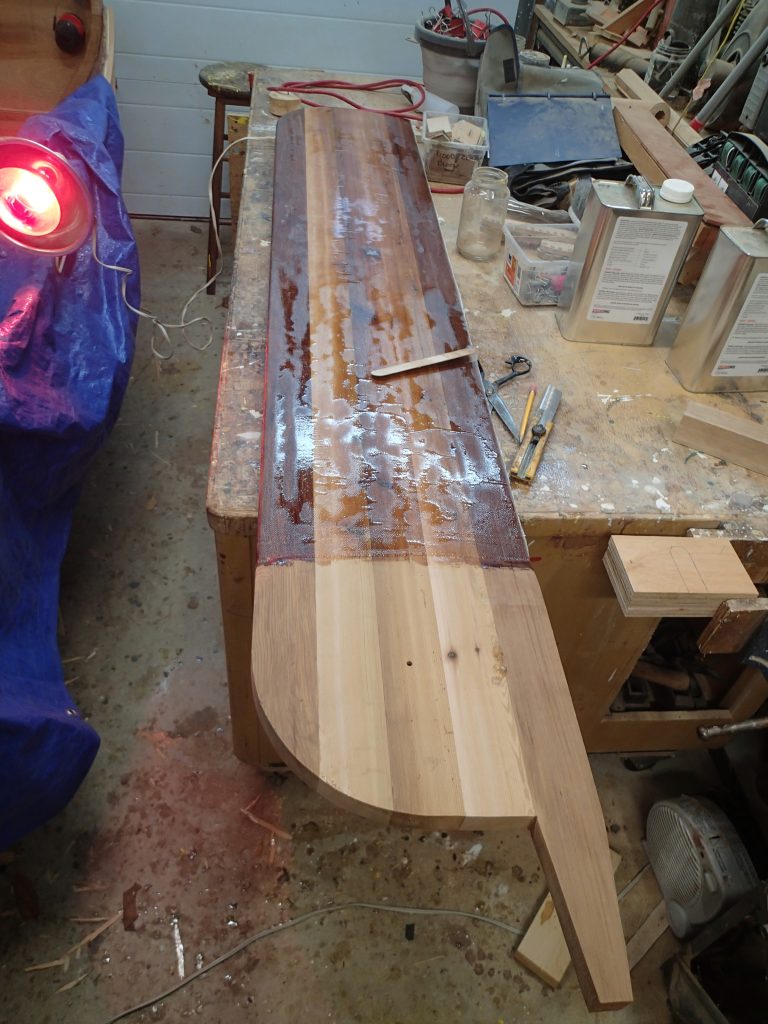
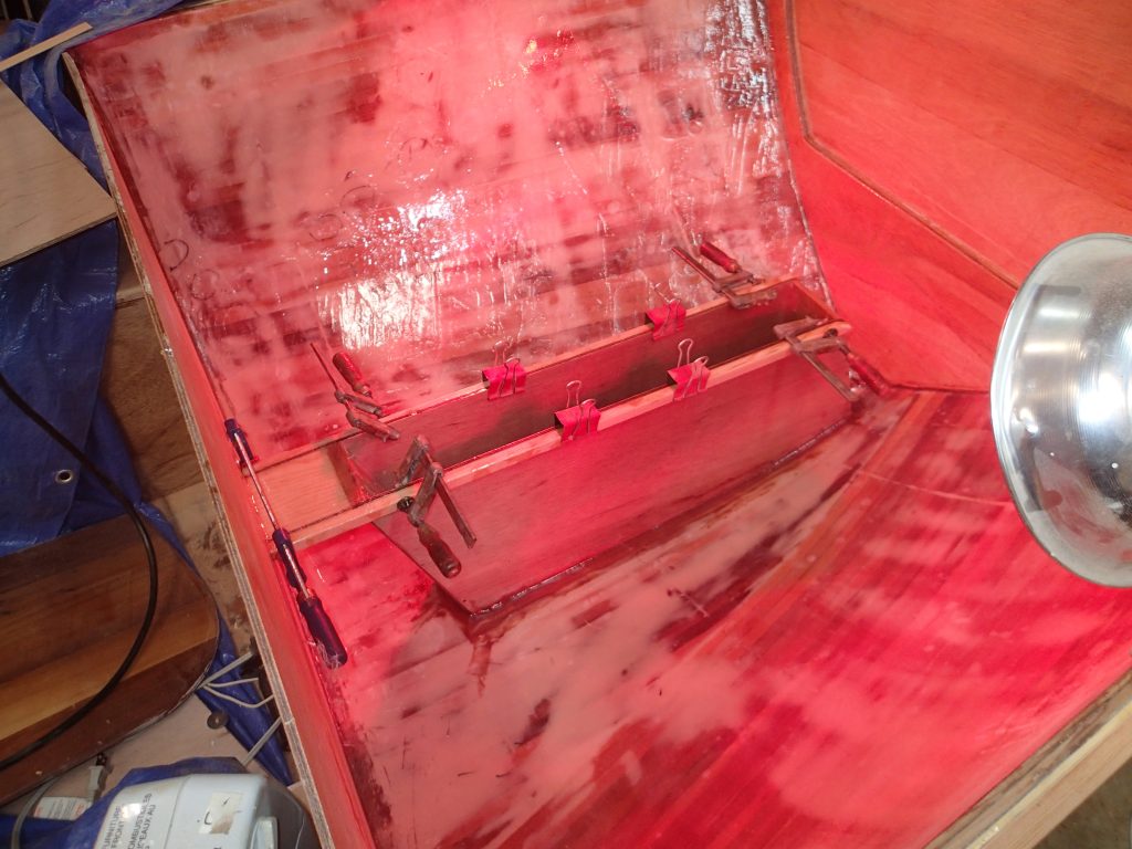
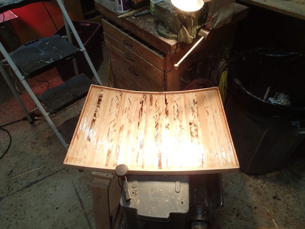
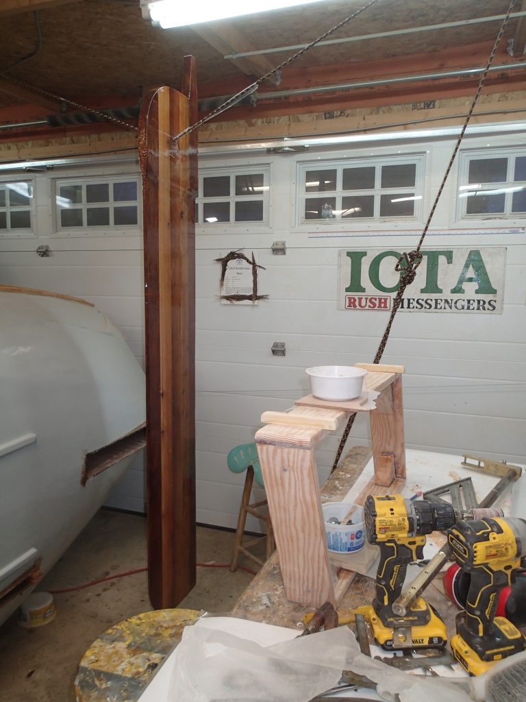
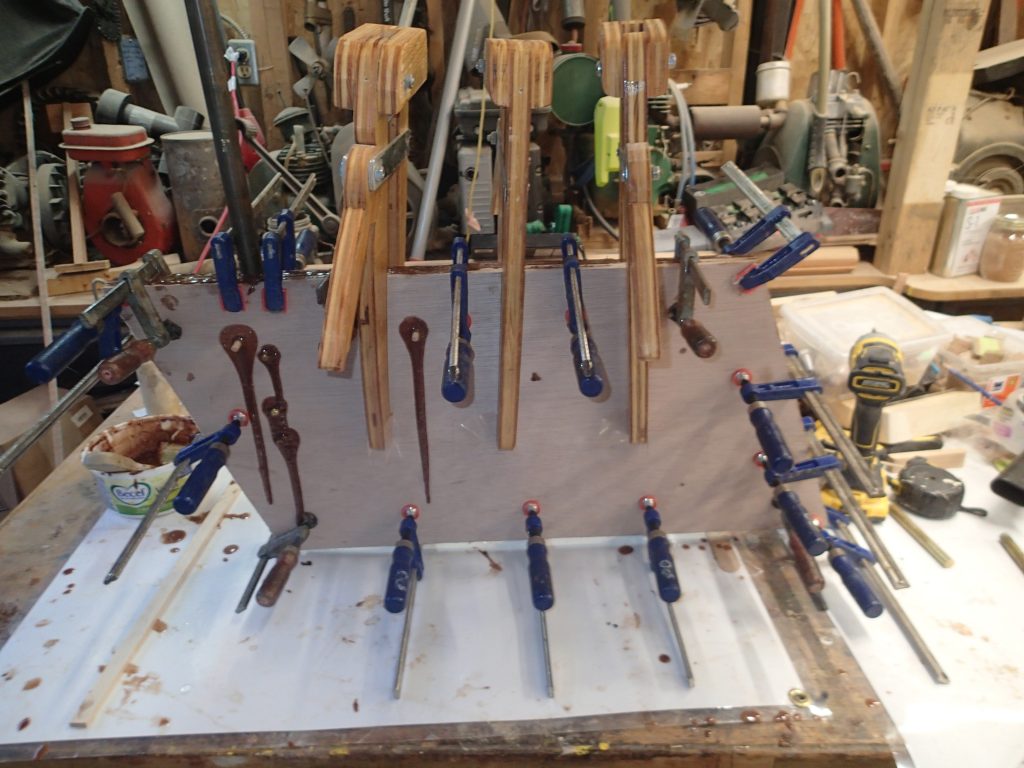
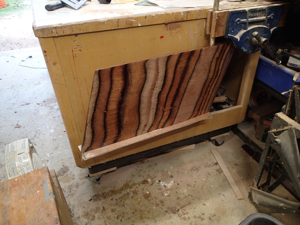
Applying the epoxy and cloth to the centreboard. I am doing it in two stages, first the main body of the centreboard. I will clamp the head in my vice while the epoxy sets.
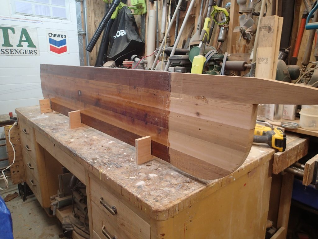
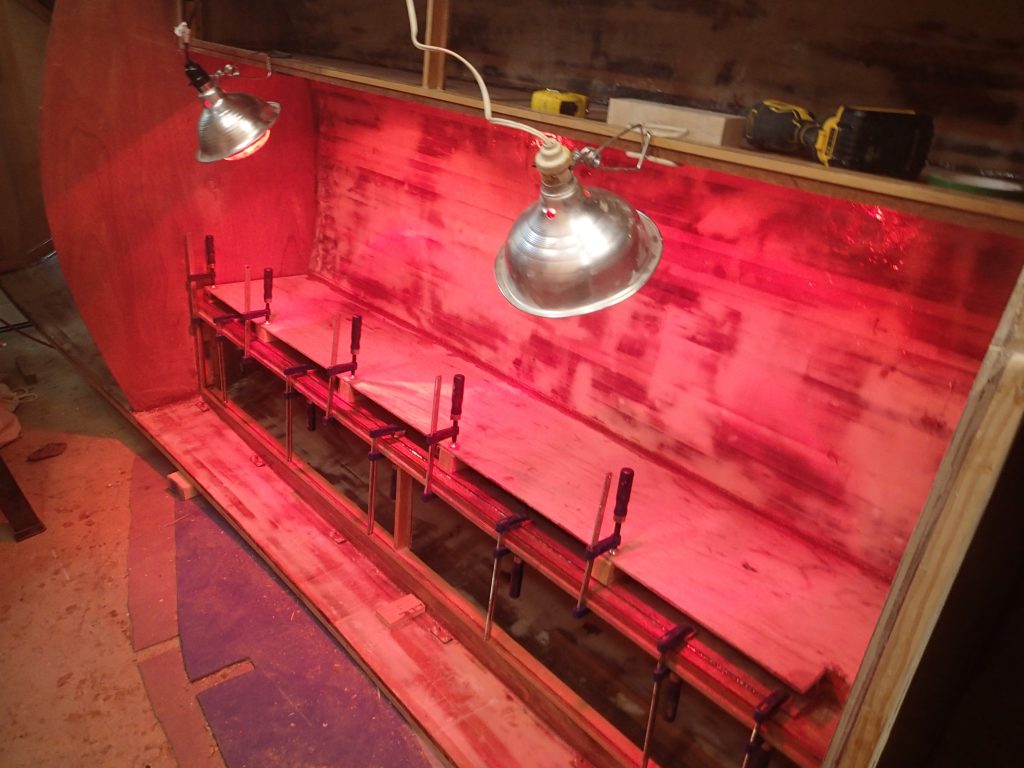
I made three stands to hold the centreboard upright while I applied the next layer of epoxy and cloth.
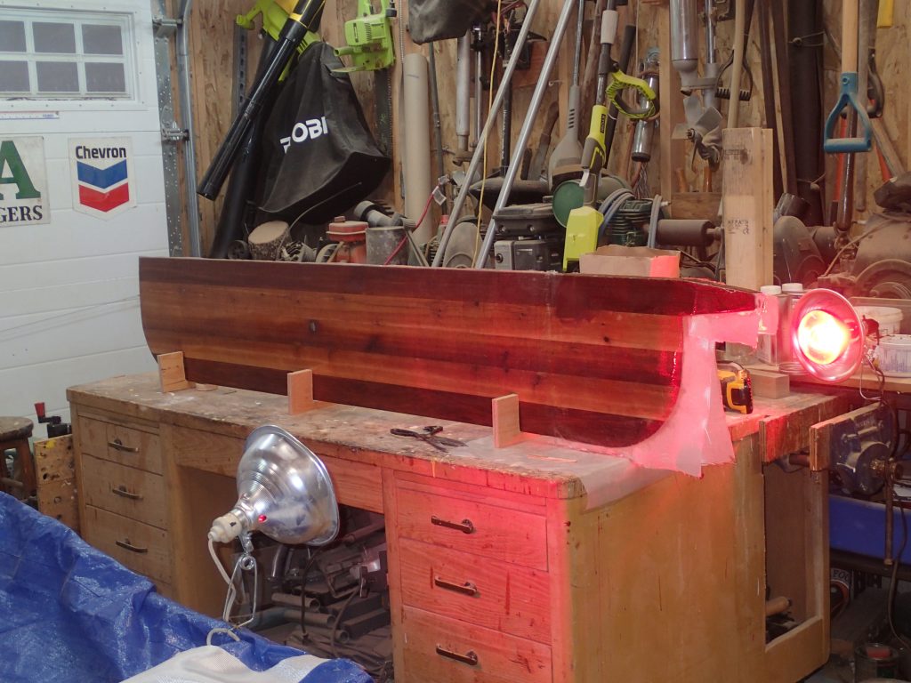
Heat lamps keep the epoxy & cloth cooking.
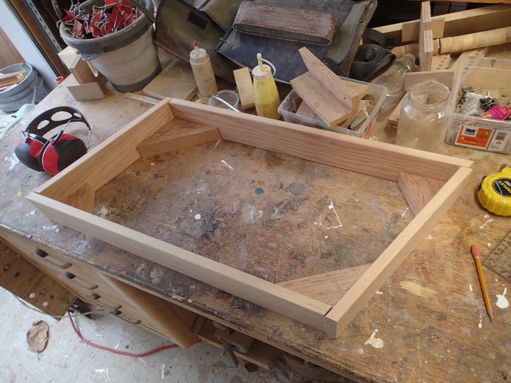
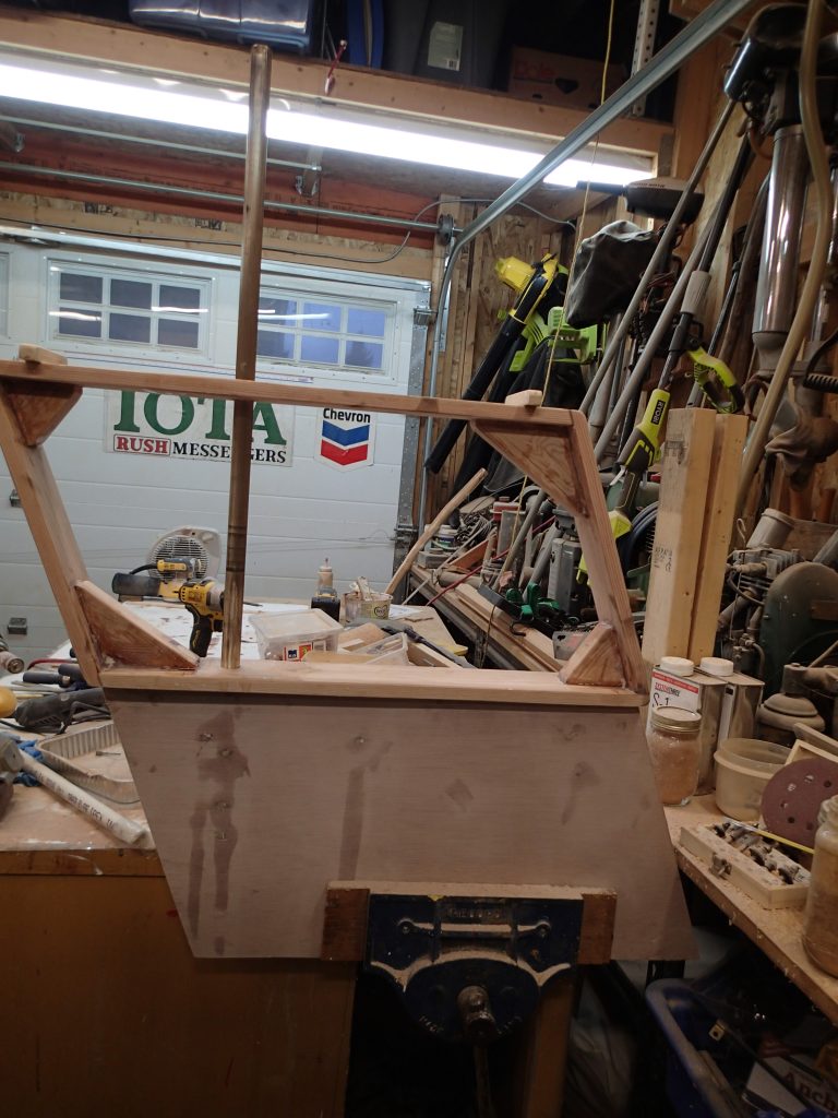
Making the frame for the rudder. This is actually a little more hard than I thought it would be. The 20° slant made everything a little harder to get right.
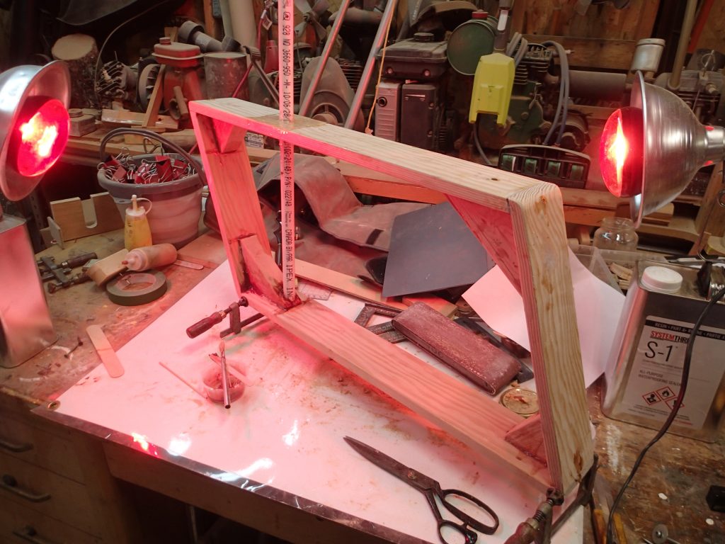
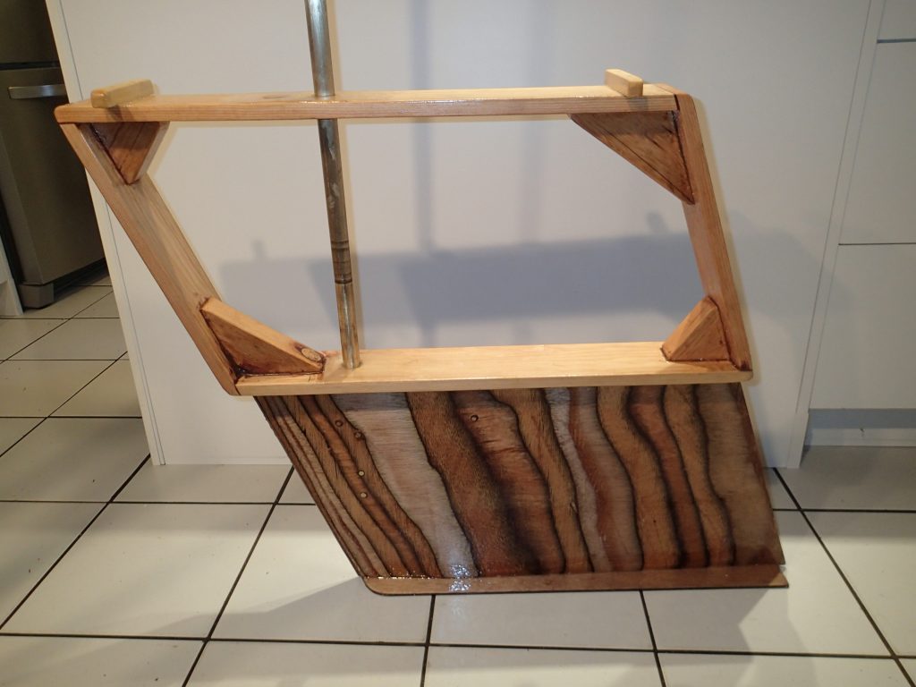
Glueing the frame up. Here is the assembled frame being epoxied up. The plastic pipe is where the rudder shaft will go. The shaft holes are reinforced with epoxy to take any wear.
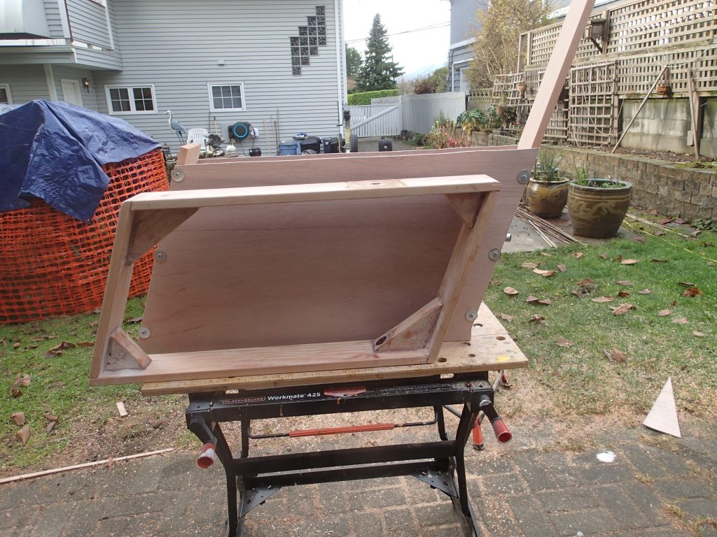
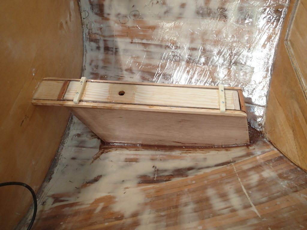
Rudder frame and case. The rudder frame fits inside of the case with about ⅛” of play on either side of the frame. I am going to dry-fit everything before I epoxy the case up and put it into the boat.
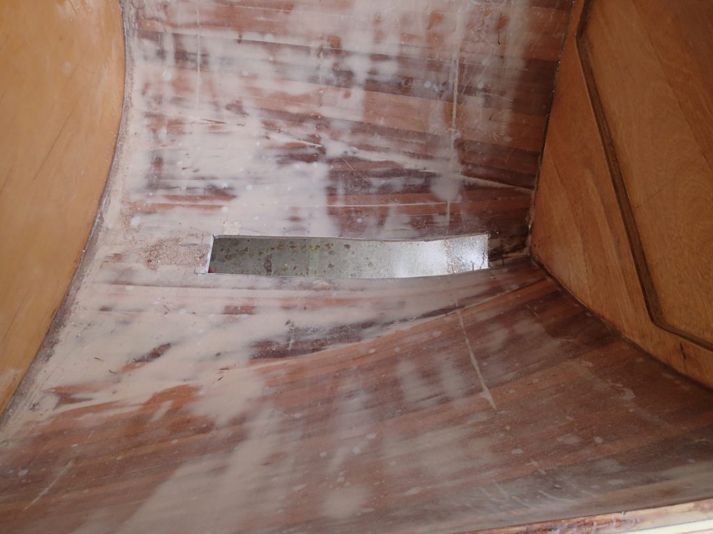
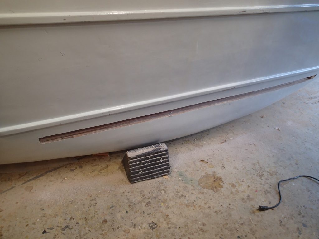
A really big hole for the rudder case. I used the rudder case to mark out the hole I needed to put into the boat for the case. It is 4″ wide!!!
Case fitting. I am doing my best to fit the case in the centre of the boat, forward enough and level.
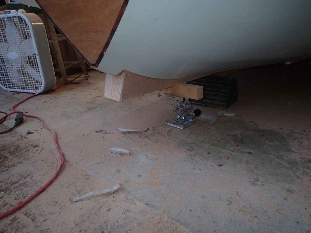
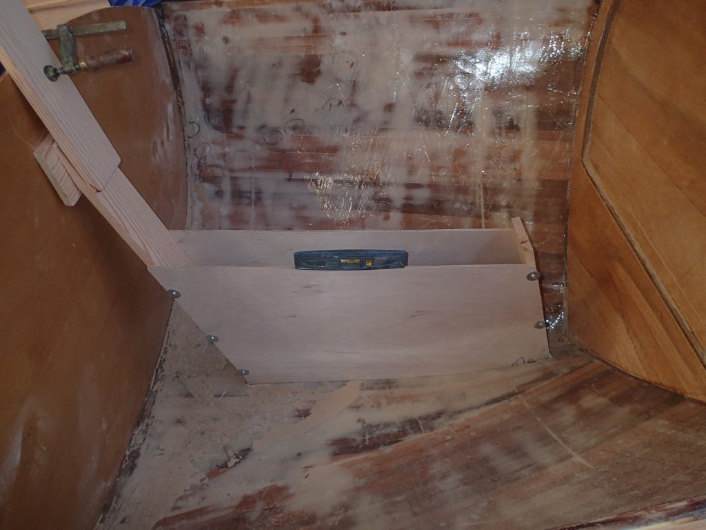
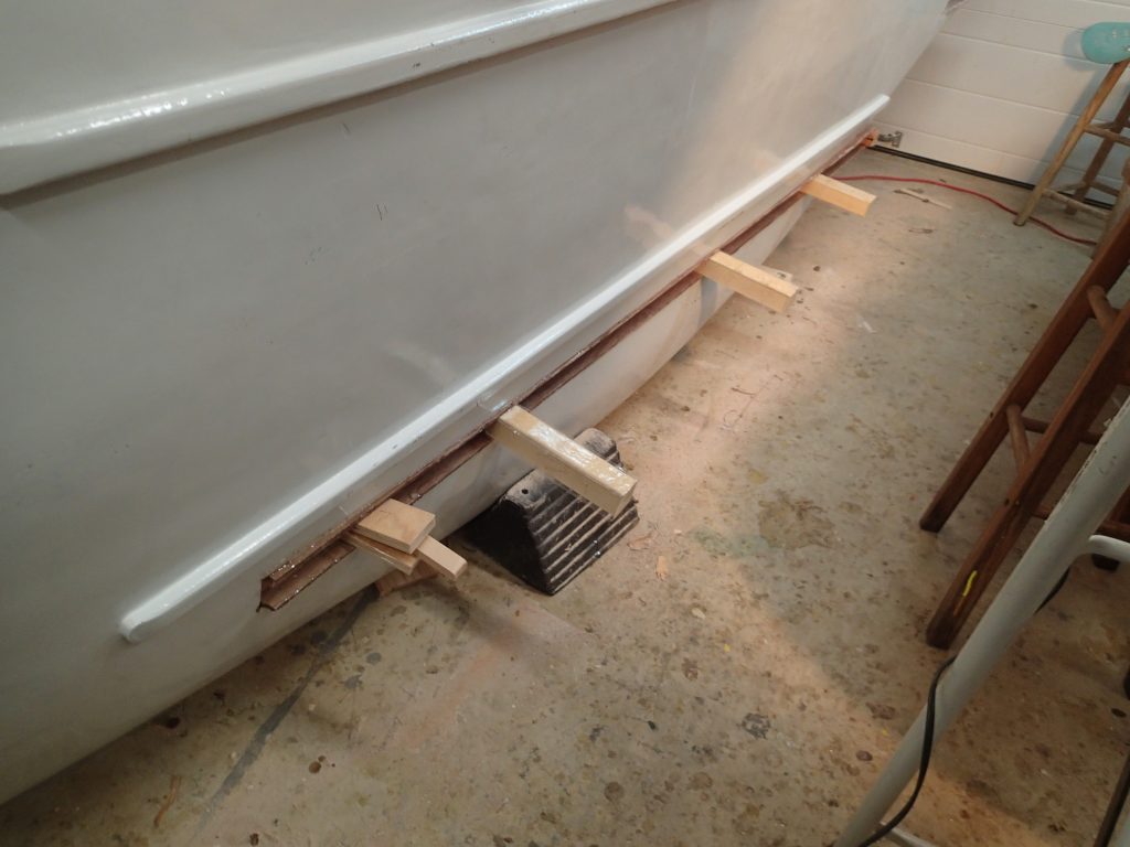
This little jackstand will hold the case far enough up. This is where I am deviating from the plans. Phil fairs the case to the hull (meaning it does not project below the hull) and states: “Filler blocking to fair frame into the upsweep of the keel aft.” I am having the case extend below the hull for two reasons:
1). When I pull my rudder up for rowing the bottom plate will seal the rudder case slot lessening turbulence. What I have to do is to fair the rudder slot into the hull. In the orginal plans, the rudder case is faired. When the rudder is brought up into the rudder case, there is no fairing and (I believe) a lot of turbulence.
2). If, in practice, this does not work, I can always to back to the plans reletively easily. Much harder to do the other way around.
Making the case. The rudder case has epoxy and cloth on every surface on the inside…for water tightness and for wear.
Waiting for the epoxy to cure sucks up the time. After the epoxy has set, I remove all of the screws, fill the holes with bamboo dowels and strip/sand all of the cloth edges.
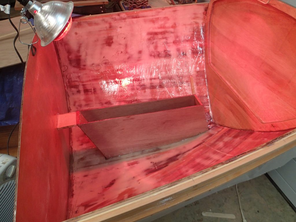
Here is the first go. I have epoxied in the case. Next is to do filets around the case and epoxy on the reinforcing strips at the top of the case.
Almost the same photo, but with the reinforcing strips and the filets in place.
Test fit of the rudder frame inside to the rudder case. The rudder case is in place. It is secured to the hull and to the bulkhead. Should be good.
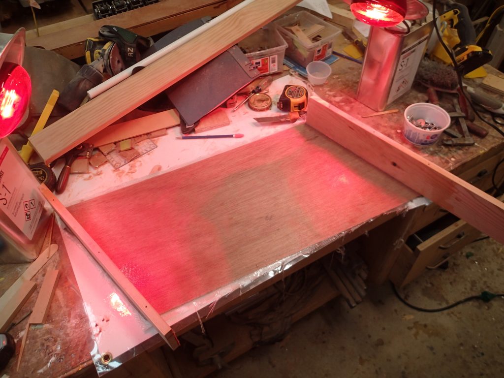
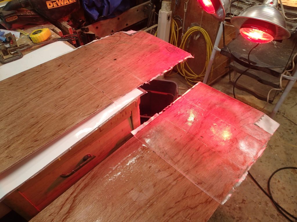
Forward hatch. Making the forward hatch. Those are left-over maple strips.
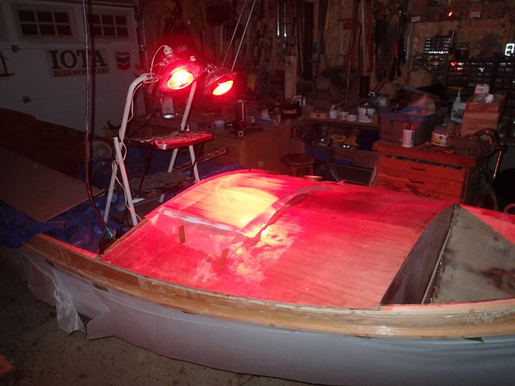
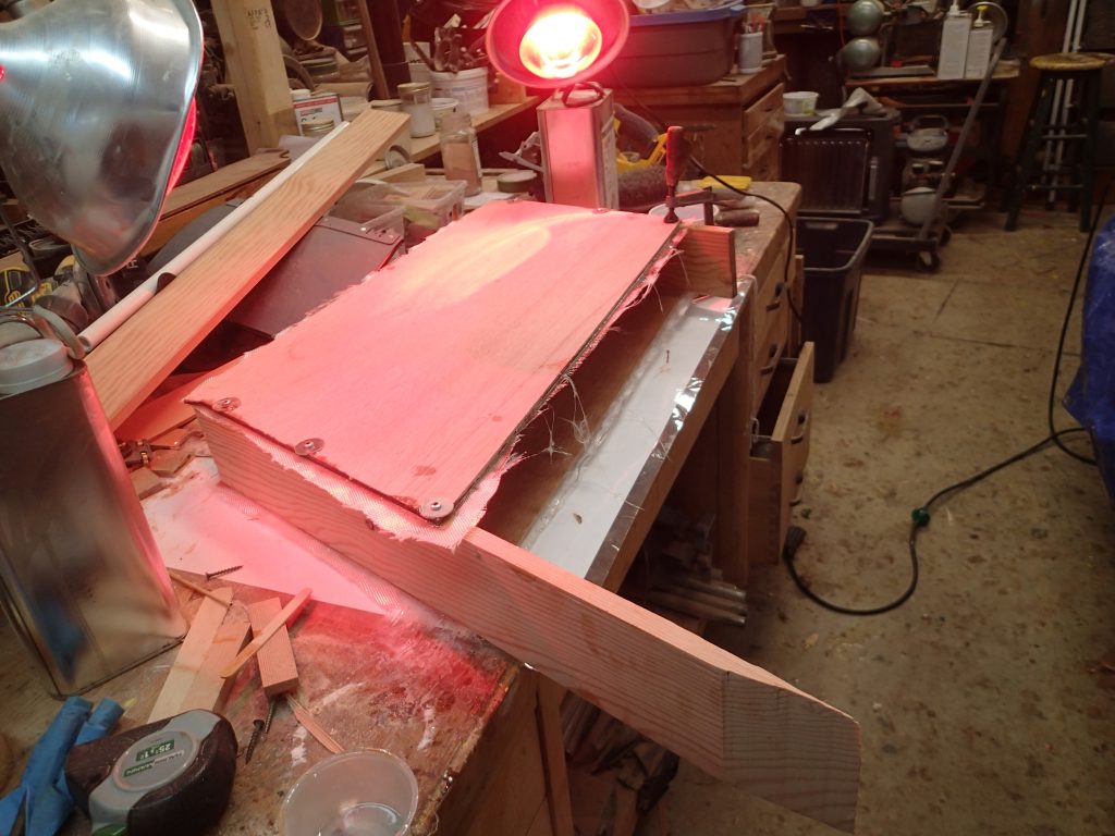
Second round on the hatch. There were four. First, glue the strips together using the coamings as a guide. Second, epoxy and cloth on the top ot the hatch. Third, epoxy on the inside of the hatch. fourth, epoxy to fill the cloth on the top of the hatch. After the first round of epoxy is set and a lot of sanding, I took off the straps and laid down (Second round) a layer of epoxy and cloth on the hatch.
I did not sand the inside of the hatch…just a layer of epoxy to lock the strips up.
Turn-over onto side. Centreboard case and centreboard test fitting. My turn-over crew arrived and we turned the boat onto its side so the centreboard case could be fitted. With the boat on its side, The epoxy I use to glue the case to the front of the seat will not run out of the joint.
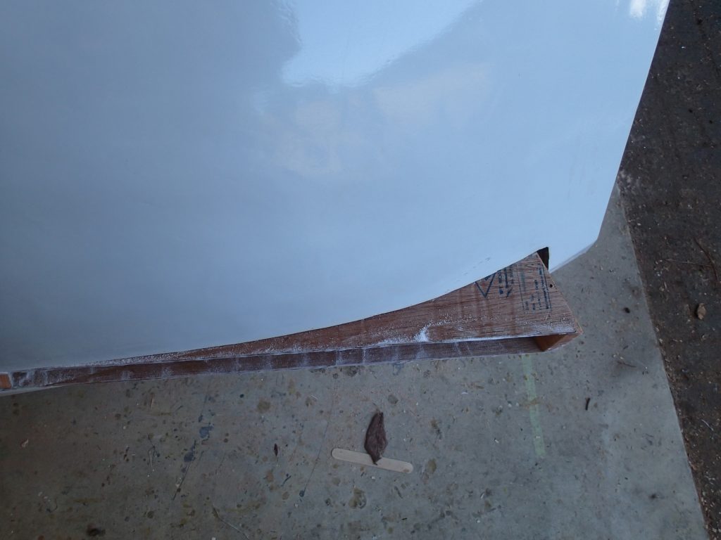
Rudder case. The rudder case protrudes through the hull. I will fair this out.
Centreboard case glue-up. The centreboard case gets the epoxy treatment with a slight change. Only the head of the case, where I expect any wear to be, gets the cloth layer.
Test fit of the centreboard case and centreboard. This is to make sure that the case (and board) fit into the side with enough room to function and that the piviot point is at the centre of lateral resistance marked on the plans.
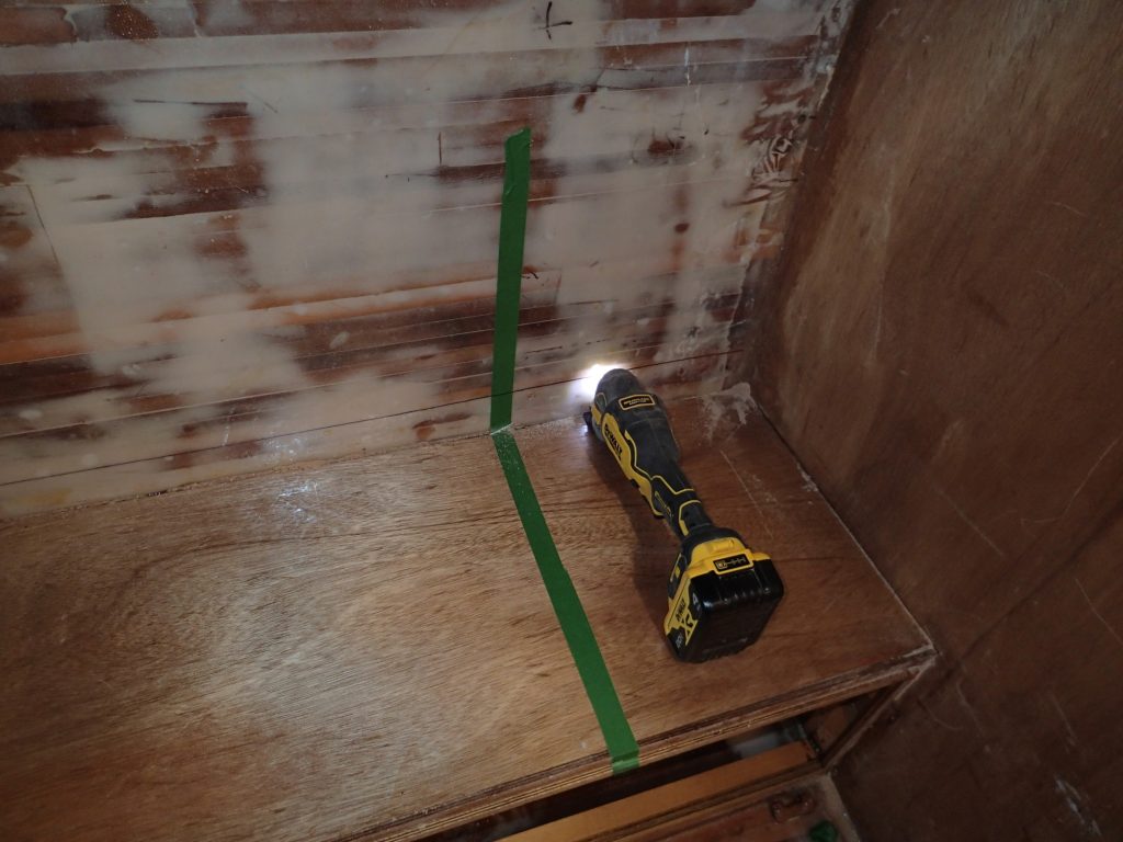
Cutting the slot for the centreboard case. I am using my new oscillating tool to cut out the centreboard case slot. I went through two blades doing it. Worked really well.
Punching through. It is a little nerve-racking to cut another big hole in your boat.
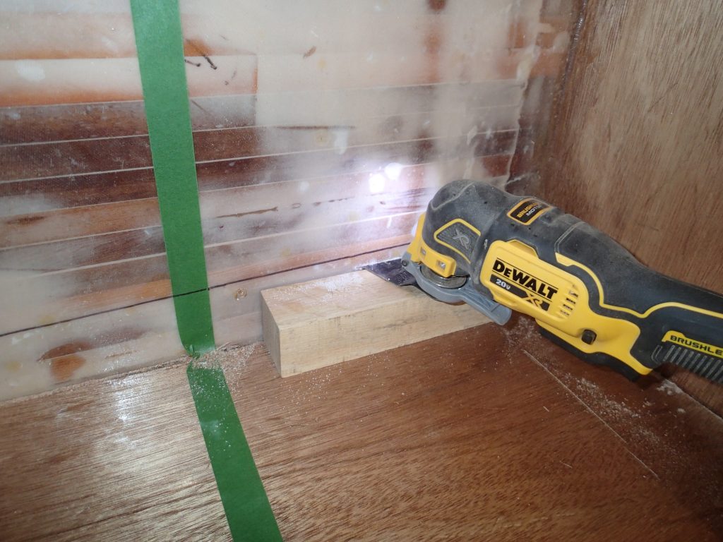
Cutting guide block. Because the centreboard case is a little floopy, I am using a block to get the correct height for the case to fit.
Slot cut-out and test fitting. With the cuts made, I check out the case and find that it fits fine. With the piece of the hull I cut out, I do not find any voids in the glue-up. I am happy that it seems as if the hull strip glue-up worked very well and the hull is solid. It is ⁹⁄₁₆” thick with the epoxy and cloth coating. This does mean, however, that the hull will weigh more than two hundred pounds specified in the plans!
Epoxying the case in. To do this, I thickened my epoxy with wood dust and used a notched trowel to apply the epoxy mixture. The case is clamped to the seat front and I used blocks the same thickness as the inside of the case to apply camping pressure in the middle of the case.
Wedges and blocks. To insure that the case was tight to the slot, I used blocks and wedges to clamp the sides of the case to the slot in the hull. I will later trim the case flush with the hull. A layer of epoxy and tape will seal the case to the hull.
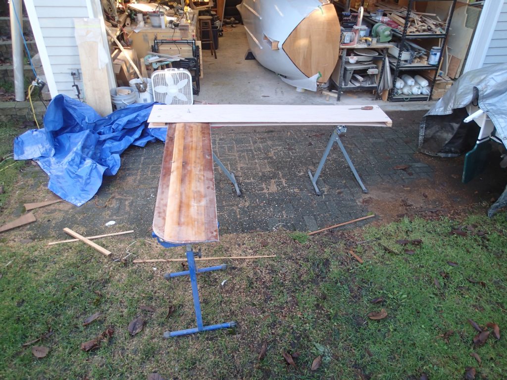
More epoxying. The centreboard gets a few more coats of resin so I can sand it smooth. I discovered that I had made the rudder shaft hole too far forward in the frame so I filled the shaft holes and made new ones. (under the margarine tubs)
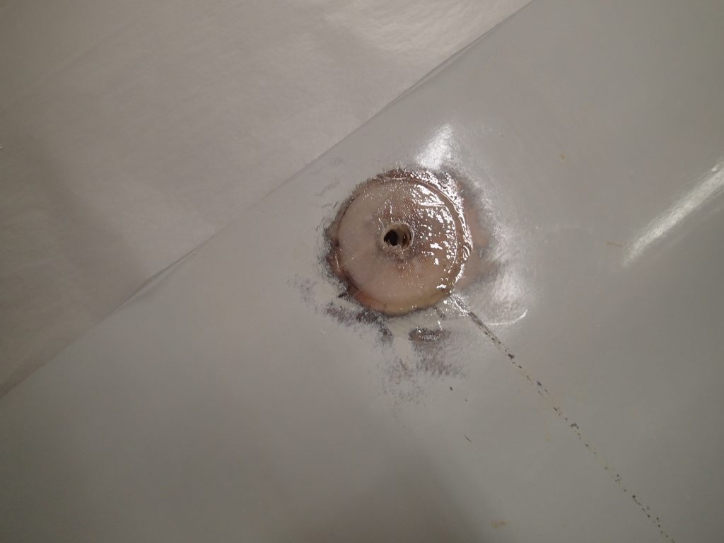
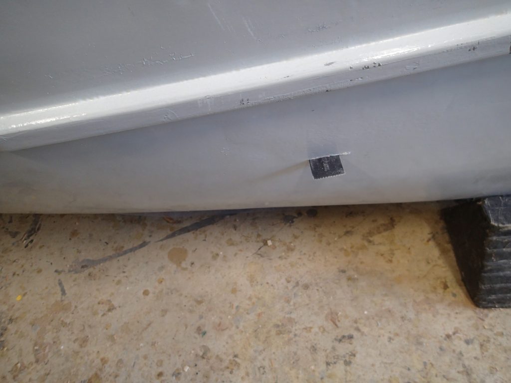
Forward compartment drain hole. I am using any left-over epoxy resin to reinforce the forward compartment drain holes. Two more layers of cloth and a little sanding. I will touch-up the paint later.
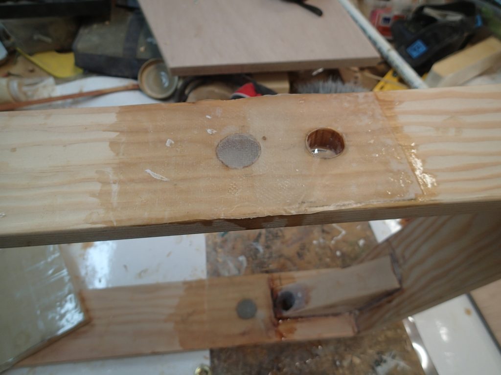
New shaft holes. Here I am reinforcing the new shaft holes. (on the left)
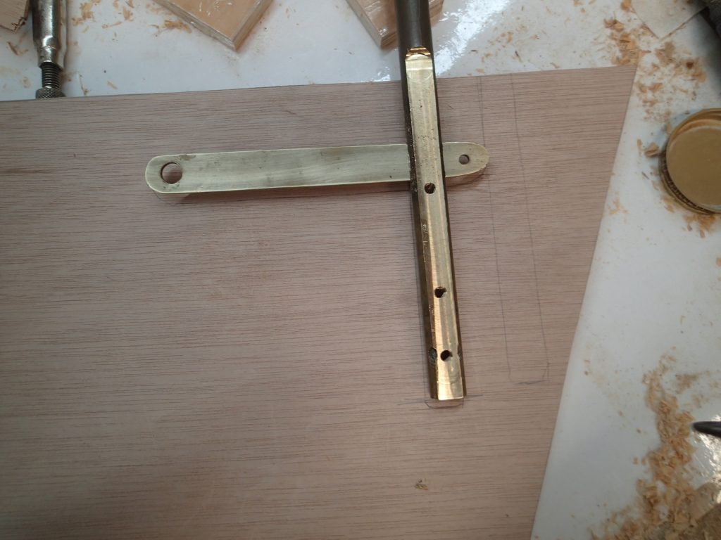
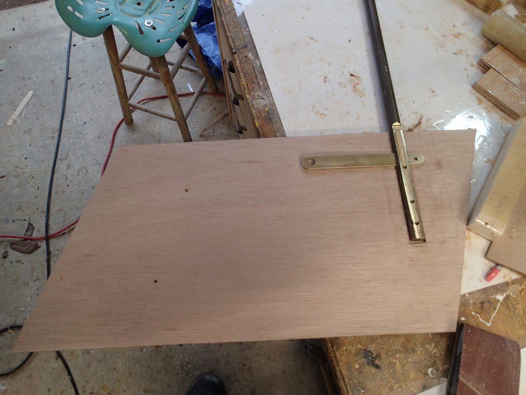
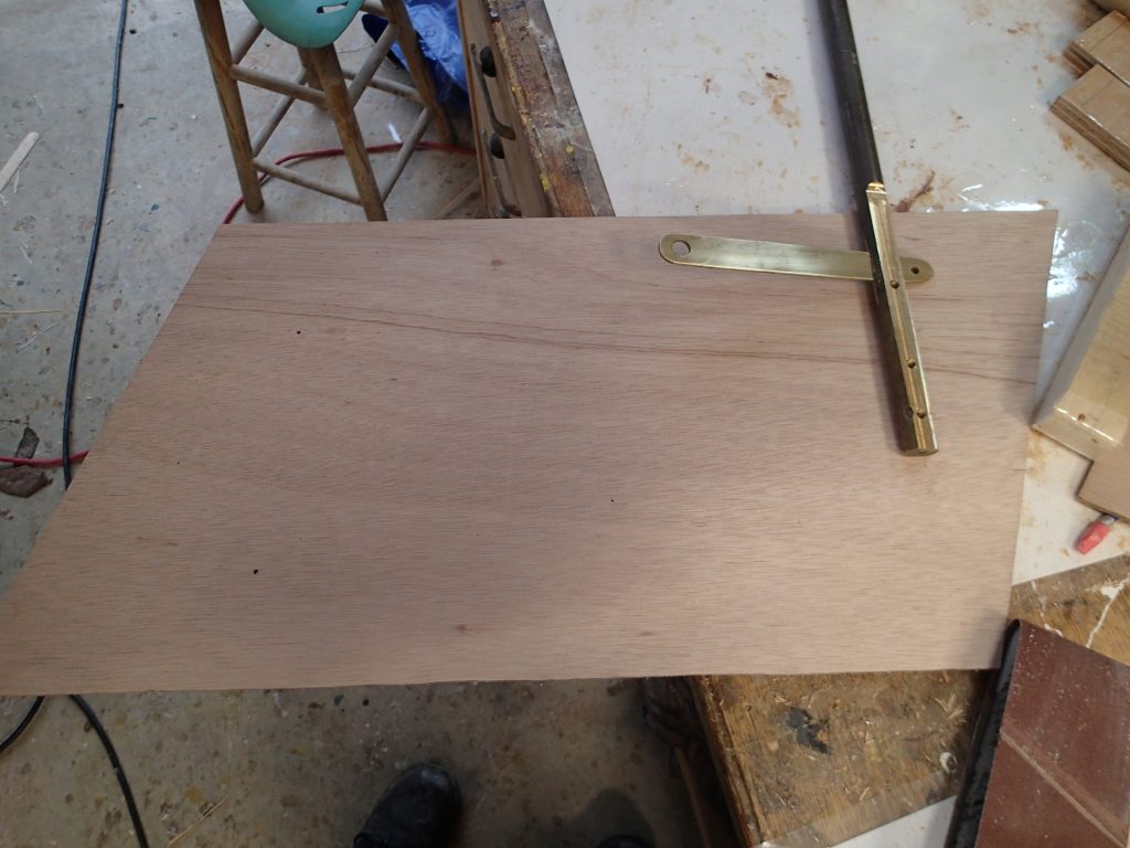
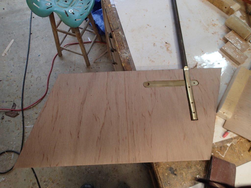
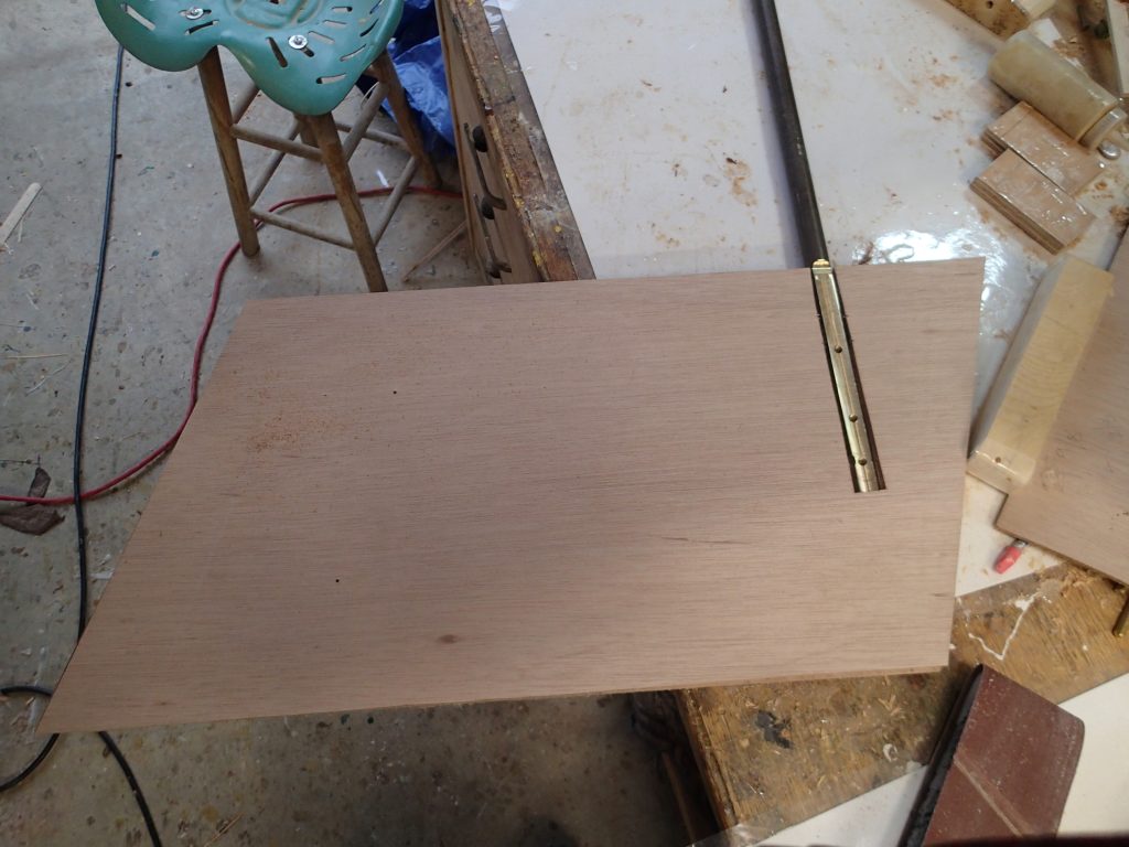
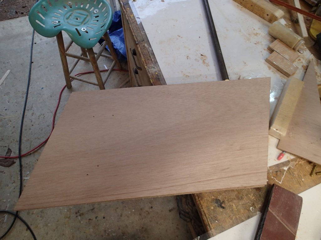
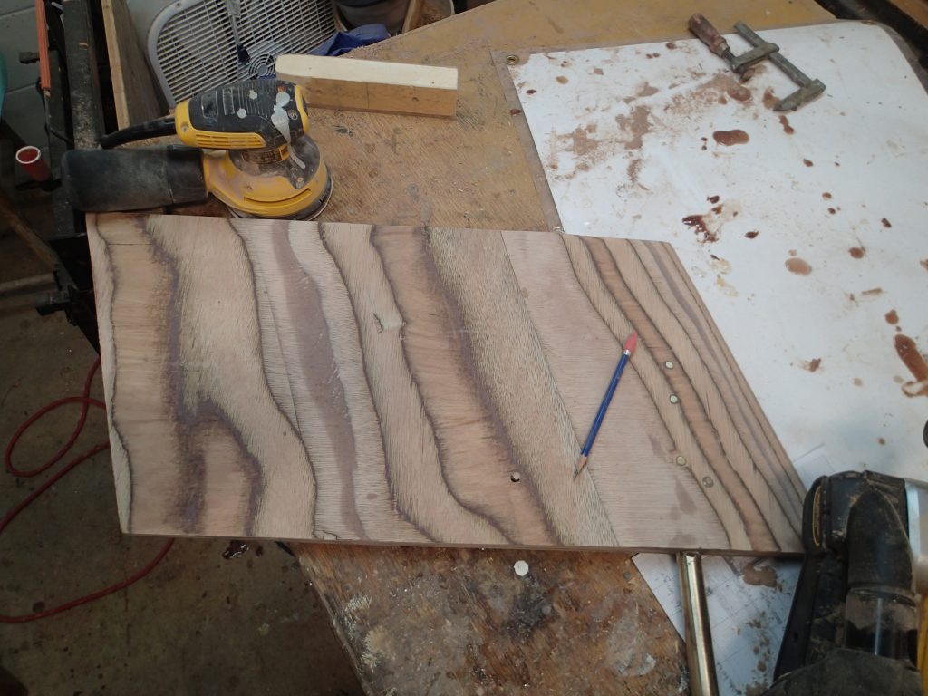
Making the rudder. Here I am marking the rudder for the rudder shaft in the correct spot. (bad spot to the right)
Rudder lay-up. The rudder is made up of five layers of 6mm marine plywood. The three middle layers are cut-out for the rudder shaft and the arm-bar. The arm-bar strengthens the connection between the shaft and the rudder layers.
Layer one…no Cut-out.

Layer two, Cut-out for shaft only.
Layer three…Cut-out for shaft and arm.
Layer four…Cut-out for shaft only.
Layer five…No cut-out.
Glue-up. Here is the glue-up. Each layer has epoxy in it. The dowels go through the holes in the arms and the shaft had threaded holes for reinforcing threaded rods.
Rudder test fit. Well, the rudder looks good. It has the same angles as the frame and is slightly smaller to insure a good fit in the rudder case. Fairing the rudder is next.
Centreboard test fit. The centreboard fits and works well.
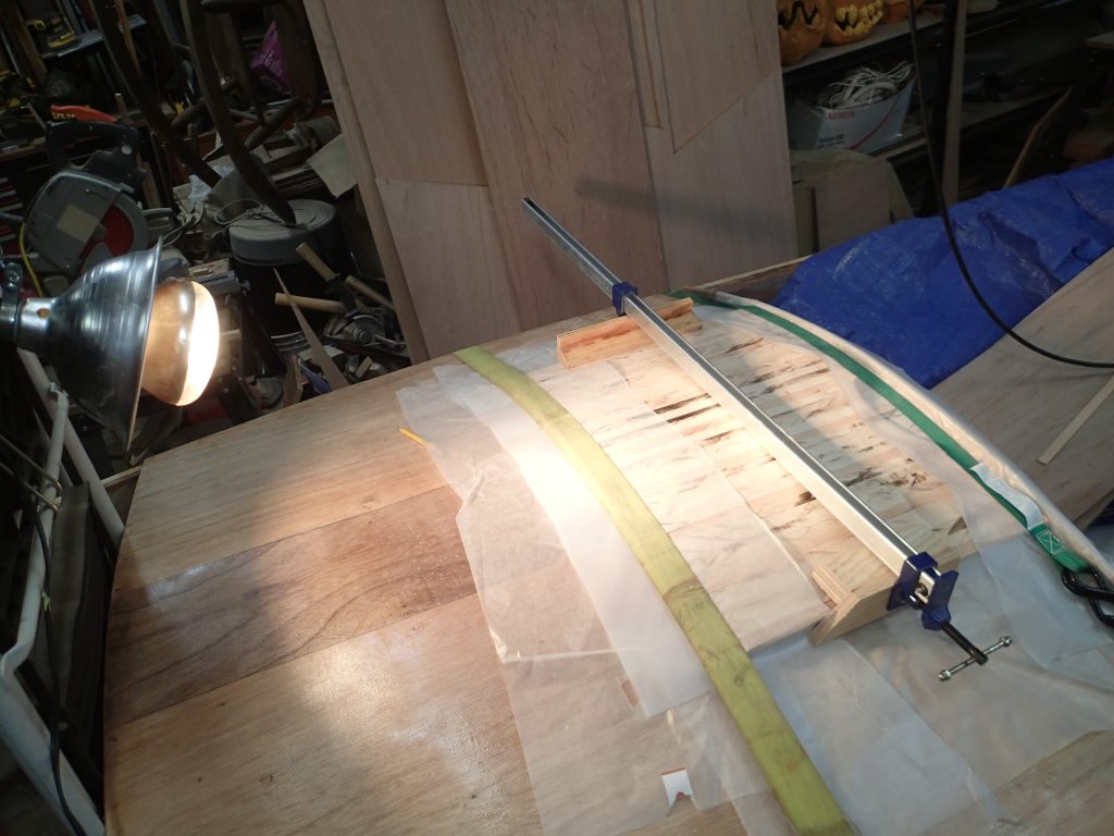
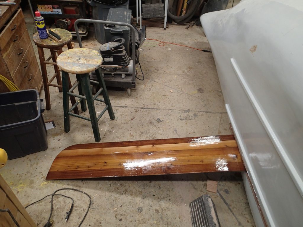
Shaping the rudder. The rudder has an air-foil shape that I do my best to duplicate. You can see the three brass pins and the two dowels in the rudder.
Epoxy coating the rudder and glueing on the bottom plate. Another slight deviation from the plans…I am using 6mm marine plywood for the bottom plate and not metal. My plate also fills the rudder case more than what is called for in the plans. Turbulence reduction!
Test fit. I am pretty happy with the way the rudder frame and rudder turned out. The old rudder shaft holes have been filled in with epoxied wine corks.
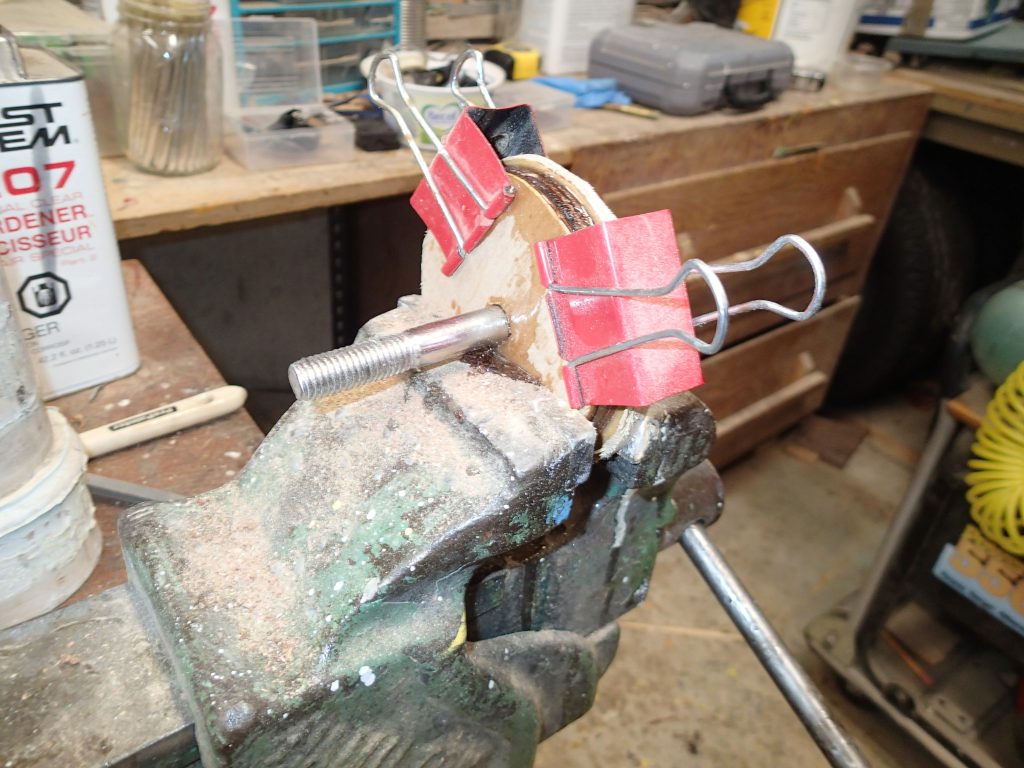
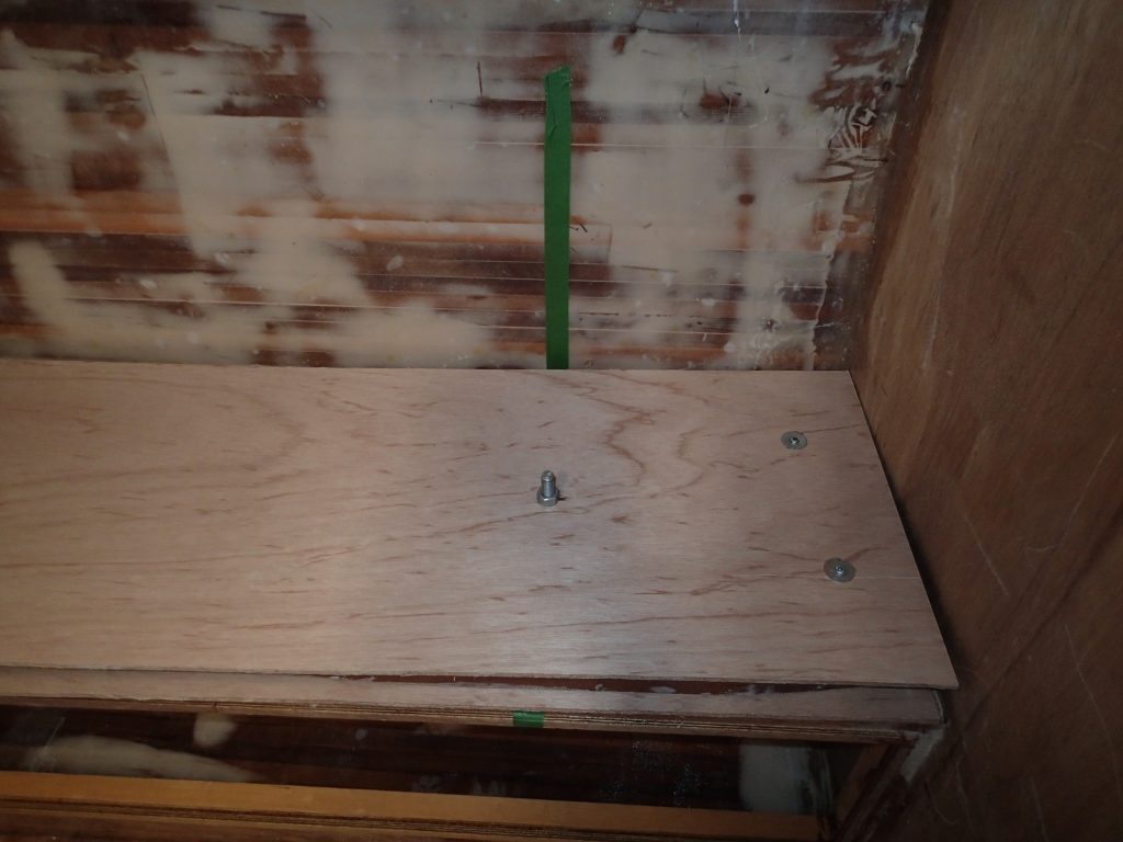
Centreboard pivot pin. I am making up a centreboard pivot pin. The centreboard will be easily removable.
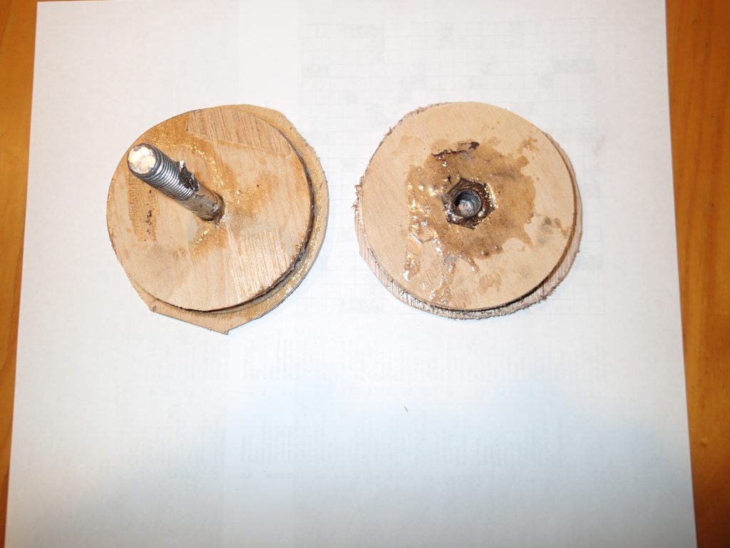
The two pieces. The piece with the nut will be epoxied onto the inside of the seat and the piece with the bolt will go through the case, the board and the seat. It will have a cork seal. A little sanding and the fittings will be ready to go in.
Thats all for now,
Mike